


368262-UIM-B-1008
20 Johnson Controls Unitary Products
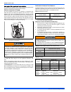
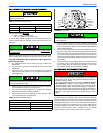
FAN-ASSISTED COMBUSTION SYSTEM
This appliance is equipped with an integral mechanical means to draw
products of combustion through the heat exchanger.
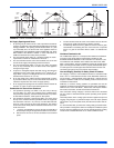
Ambient Combustion Air Supply
This type installation will draw the air required for combustion from
within the space surrounding the appliance and from areas or rooms
adjacent to the space surrounding the appliance. This may be from
within the space in a non-confined location or it may be brought into the
furnace area from outdoors through permanent openings or ducts. A
single, properly sized pipe from the furnace vent connector to the out-
doors must be provided. For upflow models combustion air is brought
into the furnace through the unit top panel opening.
An unconfined space is not less than 50 cu.ft (1.42 m
3
) per 1,000 Btu/
hr (0.2928 kW) input rating for all of the appliances installed in that
area.
Rooms communicating directly with the space containing the appli-
ances are considered part of the unconfined space, if openings are fur-
nished with openings or louvers.
A confined space is an area with less than 50 cu.ft (1.42 m
3
) per 1,000
Btu/hr (0.2928 kW) input rating for all of the appliances installed in that
area. The following must be considered to obtain proper air for combus-
tion and ventilation in confined spaces.
Combustion Air Source From Outdoors
The blocking effects of louvers, grilles and screens must be given con-
sideration in calculating free area. If the free area of a specific louver or
grille is not known, refer to Table 7, to estimate free area.
* Do not use less than 1/4”(0.635 cm) mesh
+ Free area of louvers and grille varies widely; the installer should follow
louver or grille manufacturer’s instructions.
Dampers, Louvers and Grilles (Canada Only)
1. The free area of a supply air opening shall be calculated by sub-
tracting the blockage area of all fixed louvers grilles or screens
from the gross area of the opening.
2. Apertures in a fixed louver, a grille, or screen shall have no dimen-
sion smaller than 0.25” (0.64 cm).
3. A manually operated damper or manually adjustable louvers are
not permitted for use.
4. A automatically operated damper or automatically adjustable lou-
vers shall be interlocked so that the main burner cannot operate
unless either the damper or the louver is in the fully open position.
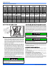
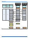
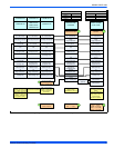
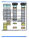
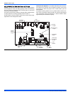
FIGURE 26: Combustion Airflow Path Through The Furnace Casing to
the Burner Compartment
This type of installation requires that the supply air to the appli-
ance(s) be of a sufficient amount to support all of the appliance(s)
in the area. Operation of a mechanical exhaust, such as an exhaust
fan, kitchen ventilation system, clothes dryer or fireplace may cre-
ate conditions requiring special attention to avoid unsatisfactory
operation of gas appliances. A venting problem or a lack of supply
air will result in a hazardous condition, which can cause the appli-
ance to soot and generate dangerous levels of CARBON MONOX-
IDE, which can lead to serious injury, property damage and / or
death.
COMBUSTION
AIR
Table 7: Estimated Free Area
Wood or Metal
Louvers or Grilles
Wood 20-25%*
Metal 60-70% *
Screens+
1/4” (0.635 cm)
mesh or larger 100%
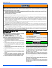
When a Category I furnace is removed or replaced, the original
venting system may no longer be correctly sized to properly vent
the attached appliances.
An improperly sized vent system can cause CARBON MONOXIDE
to spill into the living space causing personal injury, and or death.
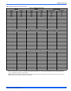
Table 8: Unconfined Space Minimum Area in Square Inch
BTUH Input Rating
Minimum Free Area in Square Feet
Required for Each Opening
60,000
60 (387 cm
2
)
80,000
80 (516 cm
2
)
100,000
100 (645 cm
2
)
120,000
120 (742 cm
2
)
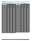
Table 9: Free Area
BTUH Input
Rating
Minimum Free Area Required for Each Opening
Horizontal Duct
(2,000 BTUH)
Vertical Duct or
Opening to Outside
(4,000 BTUH)
Round Duct
(4,000 BTUH)
60,000
30 in
2
(193 cm
2
) 15 in
2
(97 cm
2
)
5” (13 cm)
80,000
40 in
2
(258 cm
2
) 20 in
2
(129 cm
2
)
5” (13 cm)
100,000
50 in
2
(322 cm
2
) 25 in
2
(161 cm
2
)
6” (15 cm)
120,000
60 in
2
(387 cm
2
) 30 in
2
(193 cm
2
)
7” (18 cm)
EXAMPLE: Determining Free Area.
Appliance 1 Appliance 2 Total Input
100,000 + 30,000 = (130,000 ÷ 4,000) = 32.5 Sq. In. Vertical
Appliance 1 Appliance 2 Total Input
100,000 + 30,000 = (130,000 ÷ 2,000) = 65 Sq. In. Horizontal