


368262-UIM-B-1008
Johnson Controls Unitary Products 19
ACCESSORY CONNECTIONS
The furnace control will allow power-switching control of various acces-
sories.
ELECTRONIC AIR CLEANER CONNECTION
Two 1/4” (0.64 cm) spade terminals (EAC and NEUTRAL) for electronic
air cleaner connections are located on the control board. The terminals
provide 115 VAC (1.0 amp maximum) during circulating blower opera-
tion.
HUMIDIFIER CONNECTION
Two 1/4” (0.64 cm) spade terminals (HUM and NEUTRAL) for humidi-
fier connections are located on the control board. The terminals provide
115 VAC (1.0 amp maximum) during heating system operation.
A mounting hole is provided on the control panel next to the furnace
control board for mounting a humidifier transformer if required.
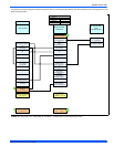
HUMIDISTAT CONNECTION
For better humidity control during cooling operation, an external humi-
distat may be used. When using a external humidistat, put the HUMI-
DISTAT jumper in the “YES” position. Connect the low voltage wiring as
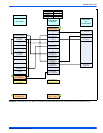
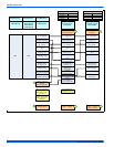
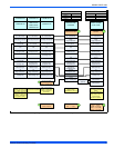
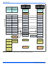
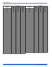
shown in Figures 19-24, Thermostat Charts.
ZONING OPERATION
This furnace may be used in zoning systems, using a separate after-
market zoning control. For use in zoned systems, put the ZONE CON-
TROL jumper on the furnace control board in the “YES” position.
If the Zone jumper is put in the “Yes” position, the heating load logic
switches to a special algorithm for multi-zone homes.
1. This algorithm operates at the “low demand” firing rate for 10 min-
utes and then ramps to high fire within 20 minutes (30 minutes
maximum to get to 100% firing rate).
2. The special zoning algorithm does not
have the Run 2 function, so
the burners will stop firing as soon as there is no call for heating.
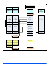
HEAT PUMP OPERATION
This furnace may be used in conjunction with a heat pump in dual fuel
applications. For heat pump applications, put the HEAT PUMP jumper
on the furnace control board in the “YES” position. Connect the low volt-
age wiring as shown in Figures 19-24, Thermostat Charts. If a two-
stage heat pump is to be used, a two-stage thermostat is required.
If the Heat Pump jumper is in the “Yes” position, it indicates that there is
a heat pump present and the furnace is used as a secondary heat
source. In addition, the “Yes” Heat Pump jumper allows the system to
read the presence of the “O” terminal signal. In heat pump operation,
the following special algorithm logic applies:
1. Supplemental Heating - When both a “W” signal and a “Y1” signal
are present, the modulating firing rate will operate as normal,
except there will be no Run 2 function, so the burners will stop fir-
ing as soon as the “W” signal is removed.
2. Defrost Cycle - When both a “W” signal and a “Y2” signal are
present, the modulating firing rate will operate at a constant 80%
firing rate and there will be no Run 2 function, so the burners will
stop firing as soon as the “W” signal is removed..
3. Hot Heat Pump - The “hot” heat pump feature will work when the
control is wired to a 2-stage thermostat and a 2-stage heat pump.
4. Hot Heat Pump - The “hot” heat pump feature will not
work when
the control is wired to a single-stage
thermostat and a 2-stage heat
pump.
TWINNING
These furnaces are not to be twinned. If more than one furnace is
needed in an application, each furnace must have its own complete
duct system and its own wall thermostat.
SECTION VI: VENT SYSTEM
VENT CONNECTIONS
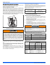
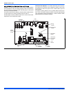
Figure 25 shows the furnace as it is shipped from the factory. To convert
to a horizontal or downflow position, remove the four screws that secure
the inducer assembly and rotate 90° being careful not to damage the
gasket. Reinstall screws. Remove cap from appropriate vent outlet
location on the cabinet cut insulation in cabinet to same size as the hole
provided and reinstall cap in the hole in the top panel.
CATEGORY 1 - 450 F. MAX. VENT TEMP.
The venting system must be installed in accordance with Section 5.3,
Air for Combustion and Ventilation, of the National Fuel Gas Code
Z223.1/NFPA 54 (latest edition), or Sections 7.2, 7.3 or 7.4 of CSA
B149.1, National Gas and Propane Codes (latest edition) or applicable
provisions of the local building code and these instructions.
The furnace shall be connected to a type B vent connector, and
shall be connected to a type B vent only. The furnace shall not be
connected to a chimney flue serving a separate appliance
designed to burn solid fuel. Single-wall vent pipe is not allowed.
It is recommended that the appliance is installed in a location where the
space temperature is 32 °F (0°C) or higher. If the appliance is installed
in a location where the ambient temperature is below 32 °F (0°C), the
combustion byproducts could condense causing damage to the appli-
ance heat exchanger.
This appliance may be common vented with another gas appliance for
residential installations as allowed by the codes and standards listed in
these instructions.
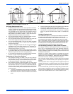
VENTING
Category I venting consists of vertically venting one or more appliances
in B-vent or B-vent connectors. Type B-vent system extends in a gen-
eral vertical direction and does not contain offsets exceeding 45°. A
vent system having not more than one 60° offset is permitted.
VENTING INTO AN EXISTING CHIMNEY
This furnace may not be vented directly into an unlined or clay tile-lined
masonry chimney. This furnace may be vented into a masonry chimney
if a double-wall metal chimney liner is used and the liner is properly
sized according to the requirements of the National Fuel Gas Code or
in Canada, the B-149 Installation Codes.
In downflow applications, do not block the combustion air inlet. The
furnace must be installed on a coil cabinet or subbase to allow com-
bustionair to enter the burner compartment.
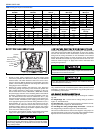
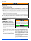
FIGURE 25: Combustion Air Inducer
COMBUSTION AIR INDUCER
90° 90°
Mounting Screw
(Remove)
Flue Transition
(Do Not Remove
)
Mounting Screw
(Remove)
Pressure
Switch
Pressure Switch
Tube Routing