


368262-UIM-B-1008
Johnson Controls Unitary Products 29
SECTION IX: NORMAL OPERATION AND
DIAGNOSTICS
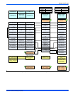
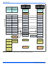
NORMAL OPERATION SEQUENCE
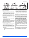
The furnace control calculates the optimum firing rate each time the
wall thermostat R and W contacts close or open (at the beginning and
at the end of each call for heat) based on information from the thermo-
stat and past demand. UNLIKE CONVENTIONAL SYSTEMS, THE
WALL THERMOSTAT DOES NOT SIMPLY TURN THE FURNACE ON
AND OFF. THE FURNACE CONTROL CALCULATES THE DEMAND
AND MAY CONTINUE TO FIRE THE FURNACE DURING PORTIONS
OF THE THERMOSTAT "OFF" CYCLE.
When the wall thermostat R and W contacts close, indicating a call for
heat, the following sequence occurs:
1. The inducer is energized and ramps up its speed until airflow is
proven by the pressure switch and by the pressure sensor on the
control board.
2. The hot surface ignitor is energized.
3. After a 17-20 second igniter heat-up, the gas valve opens and the
burners light.
4. When the control senses that flame is present, the circulating
blower starts at low speed.
5. The furnace fires at 70% of full rate for 30-45 seconds, then drops
to the minimum (50%) firing rate.
6. The firing rate is automatically adjusted to meet demand, increas-
ing gradually to maximum (100%) firing rate if the thermostat is not
satisfied within a defined time.
7. When the thermostat R and W contacts open (thermostat is satis-
fied) the furnace control recalculates the demand and a new firing
rate.
a. If demand exceeds the minimum firing rate, the burners will
continue to fire at a recalculated reduced firing rate, decreas-
ing if the thermostat remains off for a defined time.
b. If demand does not exceed the minimum firing rate, the burn-
ers will shut off immediately.
8. After the burners shut off, the circulating blower will continue to run
until the temperature sensor detects that the supply air tempera-
ture has dropped to the desired level, which should take from 30 to
90 seconds.
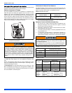
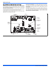
FURNACE CONTROL DIAGNOSTICS
This furnace has built-in self-diagnostic capability. If a system problem
occurs, a flashing LED shows a fault code. The LED can flash red,
green or amber to indicate various conditions. The LED is located on
the furnace control board and can be seen through the clear view port
in the lower door of the furnace. To indicate an error condition, the LED
will turn on for 1/4 second and off for 1/4 second. The pattern will be
repeated the number of times equal to the flash code. For instance, a
"six flash code" will be indicated by the LED turning on and off six times.
There will be a two second off period between each set of flashes. The
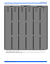
flash codes and an indication of their likely causes are listed below:
STEADY OFF - No 24V power to board. Check the 24 volt control cir-
cuit fuse on the board. Check the circuit breaker or fuse on the 115 volt
supply power to the furnace. Check that the 24 volt transformer.
One Green Flash - Normal Operation with no call for heat.
Two Green Flashes - Indicator for "No error codes in memory". See
Diagnostic Fault Code Storage and Retrieval section below.
Three Green Flashes - Indicator for "Error codes cleared from mem-
ory". See Diagnostic Fault Code Storage and Retrieval section below.
Rapid Green Flash - Control is in "Factory Speed-up" mode. This
mode is used only during factory run-testing of the furnace. To stop this
mode, cycle power to the furnace off and then back on.
One Amber Flash - Normal operation with call for cooling.
Two Amber Flashes - Normal operation with call for heat.
Three Amber flashes - Normal operation, burner is on at end of heat-
ing cycle after wall thermostat has been satisfied.
Four Amber Flashes - Heating capacity is reduced due to restriction in
the circulating air system. Check for dirty filter or closed registers.
Five Amber Flashes - Heating capacity is reduced due to restriction in
the combustion air or vent system. Check for blocked vent/air pipe or
clogged condensate drain. Above 4,000 feet altitude, this may also indi-
cate automatic, normal derating for altitude. See page 7 for additional
high altitude information.
Six Amber Flashes - (Heat Pump applications only) Normal operation
with call for heat pump heating.
Rapid Amber Flash - Low flame sense current. Check for dirty or mis-
located flame sensor rod.
One Red Flash - Flame is present with no power being supplied to gas
valve. This can be caused by a gas valve that is slow to close or that
leaks gas through to the burners.
Two Red Flashes - Pressure switch closed with inducer pressure
below pressure switch setpoint (switch is closed when it should be
open). Check pressure switch.
Three Red Flashes - Pressure switch open with inducer pressure
above pressure switch setpoint (switch is open when it should be
closed). Check pressure switch.
Four Red Flashes - High limit switch open or defective temperature
sensor or 24 volt fuse is open. This may be caused by a dirty air filter,
improperly sized duct system, faulty blower motor, restricted circulating
airflow an open fuse on the control board.
Five Red Flashes - Rollout switch or condensate pressure switch
open. Check the rollout switch(es) on the burner assembly. It is a man-
ual reset switch. To reset, push the small button in the center of the
switch. If it cannot be reset or if the switch trips again, contact a quali-
fied serviceman.
Six Red Flashes - Current failure on modulating gas valve.
Seven Red Flashes - Lockout due to no ignition. The control will try
three times for ignition. If flame cannot be established in three tries, the
control will lockout for one hour and then will try again to light. Check
gas supply, ignitor, gas valve, flame sensor.
Eight Red Flashes - Lockout due to too many flame recycles. This
flash code occurs if flame is lost five times during a single heating cycle.
This could be caused by a faulty gas valve, low gas pressure, or dirty
flame sensor. The control will lock out for one hour and then will try
again.
Nine Red Flashes - Reversed line polarity or improper grounding.
Check polarity of the incoming power to the furnace. Check the ground-
ing of the furnace, including the transformer ground and the L1 and
neutral connections.
Ten Red Flashes - Gas valve circuit shorted. Check gas valve wiring. If
correct, replace gas valve.
Eleven
Red Flashes - Main blower failure - This flash code occurs
when the main limit opens and fails to reclose within five minutes, indi-
cating that the blower motor or blower wheel has failed.
Twelve Red Flashes - ID plug is not present or not connected properly,
check for loose plug or loose wires in plug.
Steady On Red - Control fault has been detected or there is 24 volts
present without 115 volts. Check that there is 24 volts and 115 volts
being supplied to the board. If so, then the board should be replaced.
IGNITION CONTROL FLAME SENSE LEVELS
Normal flame sense current is approximately
3.7 microamps DC (µa)
Low flame signal warning starts at 1.5 microamps.
Low flame signal control lockout point is
0.1 microamps DC (µa)