


368262-UIM-B-1008
28 Johnson Controls Unitary Products
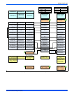
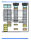
Delay Taps Selection
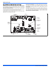
The set of jumper pins on the control board labeled "DELAY" are used
to set the delay profiles for the furnace. These can be chosen so as to
maximize the comfort and sound levels for various regions of the coun-
try.
Tap A is the default profile. It provides a 30-second ramp-up from zero
airflow to full capacity and a 30-second ramp-down from full capacity
back to zero airflow. Whenever there is a change in airflow mode, such
as from low heat to high heat, the motor will take 30 seconds to ramp
from one speed to the other.
Tap B is the humid profile. This profile is best-suited for installations
where the humidity is frequently very high during cooling season, such
as in the southern part of the country. On a call for cooling, the blower
will ramp up to 50% of full capacity and will stay there for two minutes,
then will ramp up to 82% of full capacity and will stay there for five min-
utes, and then will ramp up to full capacity, where it will stay until the
wall thermostat is satisfied. In every case, it will take the motor 30 sec-
onds to ramp from one speed to another.
Tap C is the dry profile. This profile is best suited to parts of the country
where excessive humidity is not generally a problem, where the sum-
mer months are usually dry. On a call for cooling the motor will ramp up
to full capacity and will stay there until the thermostat is satisfied. At the
end of the cooling cycle, the blower will ramp down to 50% of full capac-
ity where it will stay for 60 seconds. Then it will ramp down to zero. In
every case, it will take the motor 30 seconds to ramp from one speed to
another.
Tap D is the normal profile, best suited for most of the country, where
neither excessive humidity nor extremely dry conditions are the norm.
On a call for cooling, the motor will ramp up to 63% of full capacity and
will stay there for 90 seconds, then will ramp up to full capacity. At the
end of the cooling cycle, the motor will ramp down to 63% of full capac-
ity and will stay there for 30 seconds, then will ramp down to zero. In
every case, it will take the motor 30 seconds to ramp from one speed to
another.
Humidistat
When a humidistat is installed in the system, the “Humidistat” jumper on
the control board should be moved to the “YES” position. The cooling
airflow will then be reduced by 15% whenever the humidistat indicates
high humidity.
SECTION VIII: SAFETY CONTROLS
CONTROL CIRCUIT FUSE
A 3-amp fuse is provided on the control circuit board to protect the 24-
volt transformer from overload caused by control circuit wiring errors.
This is an ATO 3, automotive type fuse and is located on the control
board.
BLOWER DOOR SAFETY SWITCH
This unit is equipped with an electrical interlock switch mounted in the
burner compartment. This switch interrupts all power at the unit when
the panel covering the blower compartment is removed.
Electrical supply to this unit is dependent upon the panel that covers the
blower compartment being in place and properly positioned.
ROLLOUT SWITCH CONTROLS
These controls are mounted on the burner assembly. If the temperature
in the burner area exceeds its set point, the ignition control and the gas
valve are de-energized. The operation of this control indicates a mal-
function in the combustion air blower, heat exchanger or a blocked vent
pipe connection. Corrective action is required. These are manual reset
controls that must be reset before operation can continue.
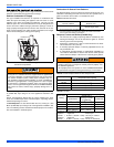
PRESSURE CONTROLS
Pressure Sensor - This furnace is equipped with a pressure sensor in
the burner compartment near the combustion blower. This sensor mon-
itors combustion airflow through furnace and piping systems. If any of
the conditions listed below are detected by the pressure sensor, the
control board will prevent a hazardous condition from occurring by
speeding up the combustion blower motor in order to maintain ade-
quate combustion airflow. If the combustion blower is already turning at
full speed, the furnace control will then start reducing the input to the
furnace in order to maintain proper combustion with the amount of com-
bustion airflow available. If there is not enough combustion air available
to give proper combustion even at the minimum input rate (50%), the
control will close the gas valve and shut off the burners. The sensor will
detect the following conditions.
1. Blockage of vent piping or vent terminal
2. Failure of combustion air blower motor or blower wheel.
Pressure Switch - This furnace is equipped with a pressure switch
mounted on the furnace vestibule panel. This switch monitors the flow
through the vent system. The switch will close at the beginning of each
cycle when adequate combustion airflow is established. However, this
switch may be open under certain conditions when the burners are lit.
The pressure sensor is the primary flow sensor.
LIMIT CONTROLS
Limit Switch - This furnace is equipped with a high temperature limit
control mounted to the left side of the furnace vestibule panel. This limit
switch will open and shut off gas to the burners if it detects excessive air
temperature in the furnace, which can be caused by any of the following
conditions:
1. Dirty filter
2. Failure of the circulating blower motor or wheel
3. Too many supply or return registers closed or blocked.
Temperature Sensor - This furnace is also equipped with a tempera-
ture sensor mounted to the left side of the vestibule panel, near the limit
switch. This sensor monitors the temperature of the air being supplied
to the home. If the sensor detects air temperature higher than normal,
the furnace control will first speed up the circulating blower motor in
order to try to increase the amount of airflow being delivered, thereby
reducing the air temperature. If the blower motor is already turning at
full speed, the control will then start reducing the input to the furnace to
try to reduce the air temperature. If the supply air temperature is too
high even at the minimum input rate (50%), the control will close the
gas valve and shut off the furnace.
Main power to the unit must still be interrupted at the main power
disconnect switch before any service or repair work is to be done to
the unit. Do not rely upon the interlock switch as a main power dis-
connect.
Blower and burner must never be operated without the blower
panel in place.