


368262-UIM-B-1008
Johnson Controls Unitary Products 25
ADJUSTMENT OF MANIFOLD GAS PRESSURE
* The gas line pressure MUST BE
• 7” W.C. (1.74 kPA) for Natural Gas
• 11” W.C. (2.74 kPA) for Propane (LP) Gas
in order to obtain the BTU input specified on the rating plate and/or the
nominal manifold pressure specified in these instructions and on the
rating plate.
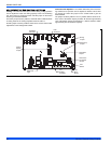
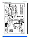
Follow the appropriate section in the instructions below. Refer to Figure
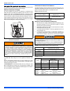
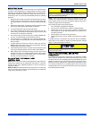
28 for a drawing of the locations of the pressure ports on the gas valve.
Turn gas off at the ball valve or gas cock on gas supply line
before the gas valve.
1. The manifold pressure must be taken at the port marked OUT
PRESS TAP.
2. The inlet gas line pressure must be taken at the port marked IN
PRESS TAP.
3. Using a 3/16” allen wrench, remove the plugs from the inlet and
outlet pressure ports. Connect a 1/8” UPT barbed hose fitting to
each pressure port.
4. Refer to Figure 28 for location of pressure regulator adjustment
cap and adjustment screws on main gas valve.
5. Turn gas and electrical supplies on and follow the operating
instructions to place the unit back in operation.
6. Adjust manifold pressure by adjusting gas valve regulator screw
for the appropriate gas per the following:
7. After the manifold pressure has been adjusted, re-calculate the
furnace input to make sure you have not exceeded the specified
input on the rating plate. Refer to "CALCULATING THE FURNACE
INPUT (NATURAL GAS)".
8. Once the correct BTU (kW) input has been established, turn the
gas valve to OFF and turn the electrical supply switch to OFF; then
remove the flexible tubing and fittings from the gas valve pressure
tap and the pressure reference hose from the burner box and
replace the pressure tap plugs. Replace the burner box front cover
(if it was removed) and place the pressure reference hose back on
the gas valve.
9. Turn the electrical and gas supplies back on, and with the burners
in operation, check for gas leakage around the gas valve pressure
port for leakage using an approved gas detector, a non-corrosive
leak detection fluid, or other leak detection methods.
ADJUSTMENT OF TEMPERATURE RISE
After about 5 minutes of operation, determine the furnace temperature
rise. Take temperature readings of both the return air and the heated air
in the ducts about six feet away from the furnace, where they will not be
affected by radiant heat. Increase or decrease the temperature rise by
changing the ATR jumper on the furnace control board. The jumper is
factory-set to deliver an air temperature rise near the midpoint of the
nameplate temperature rise range. If more air is desired (lower temper-
ature rise), move the jumper to the -10 position. If less air is desired
(higher temperature rise), move the jumper to the +10 position.
Be sure to relight any gas appliances that were turned off at the
start of this input check.
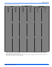
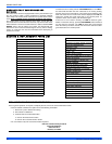
Table 11: Inlet Gas Pressure Range
INLET GAS PRESSURE RANGE
Natural Gas Propane (LP)
Minimum* 4.5” W.C. (1.12 kPa) 8.0” W.C. (1.99 kPa)
Maximum 10.5” W.C. (2.61 kPa) 13.0” (3.24 kPa) W.C.
The inlet gas pressure operating range table specifies what the
minimum and maximum gas line pressures must be for the furnace
to operate safely.
The cap for the pressure regulator must be removed entirely to gain
access to the adjustment screw. Loosening or tightening the cap
does not adjust the flow of gas.
TABLE 12:
Nominal Manifold Pressure
NOMINAL MANIFOLD PRESSURE
Natural Gas (Max) 3.5" w.c. (0.87 kPa)
Natural Gas (Min) 0.9" w.c. (0.22 kPa)
Propane (LP) Gas (Max) 10.0" w.c. (2.49 kPa)
Propane (LP) Gas (Min) 2.5" w.c. (0.62 kPa)
FIGURE 28: Gas Valve
If gas valve regulator is turned in (clockwise), manifold pressure is
increased. If screw is turned out (counterclockwise), manifold pres-
sure will decrease.
The temperature rise, or temperature difference between the return
air and the supply (heated) air from the furnace, must be within the
range shown on the furnace rating plate and within the application
limitations shown in Table 6.
The supply air temperature cannot exceed the “Maximum Supply
Air Temperature” specified in these instructions and on the fur-
nace rating plate. Under NO circumstances can the furnace be
allowed to operate above the Maximum Supply Air Temperature.
Operating the furnace above the Maximum Supply Air Temperature
will cause premature heat exchanger failure, high levels of Carbon
Monoxide, a fire hazard, personal injury, property damage, and/or
death.
Inlet
Pressure
Tap
Outlet
Pressure
Tap
On/Off
Knob
Main
Regulator
Adjustment