


518676-BIM-E-1210
58 Johnson Controls Unitary Products
NOTE: To find the Btu input, multiply the number of cubic feet
of gas consumed per hour by the Btu content of the gas
in your particular locality (contact your gas company for
this information as it varies widely from area to area).
EXAMPLE
By actual measurement, it takes 19 seconds for the hand on a 1
cubic foot dial to make a revolution with a 192,000 Btuh furnace
running. To determine rotations per minute, divide 60 by 19 =
3.16. To calculate rotations per hour, multiply 3.16 60 = 189.6.
Multiply 189.6 1 (0.5 if using a 1/2 cubic foot dial) = 189.6.
Multiply 189.6 (the Btu rating of the gas). For this example,
assume the gas has a Btu rating of 1050 Btu/ft.
3
. The result of
199,000 Btuh is within 5% of the 192,000 Btuh rating of the
furnace.
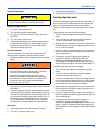
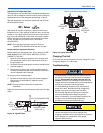
Manifold Gas Pressure Adjustment
This gas furnace has two heat stages. Therefore, the gas valve
has two adjustment screws located under a plastic protective
cover. The second stage (100% input) adjustment screw is
adjacent to the “HI” marking on the valve and the first stage
(60% input) adjustment screw is located adjacent to the “LO”
marking on the valve (See Figure 35).
Manifold pressure adjustment procedure.
Adjust second stage (100% input) pressure first, then adjust
first stage (60% input) pressure.
1. Turn off all power to the unit.
2. Using the outlet pressure port on the gas valve, connect a
manometer to monitor the manifold pressure.
3. Remove plastic cap covering HI and LO pressure
adjustment screws.
4. Turn on power to the unit.
5. Set thermostat to call for second stage heat and start
furnace.
6. If necessary, using a screwdriver, turn the
second stage
adjustment screw (adjacent to the “HI” marking on the
valve) clockwise to increase manifold pressure or
counterclockwise to decrease manifold pressure. Be sure
not to over-fire the unit on second stage.
7. After the high manifold pressure has been checked, adjust
the thermostat to call for first stage heat.
8. If necessary, using a screwdriver, turn the first stage
adjustment screw (adjacent to the “LO” marking on the
valve) clockwise to increase manifold pressure or
counterclockwise to decrease manifold pressure. Be sure
not to under-fire the unit on first stage.
9. Once pressure has been checked, replace the plastic cap
covering the HI and LO pressure adjustment screws.
NOTE: When using natural gas, the manifold pressure for
second stage (100% input) should be 3.5 IWG ± 0.3.
The manifold pressure for first stage (60% input) when
using natural gas should be 1.5 IWG ± 0.3.
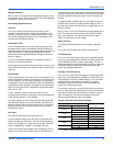
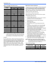
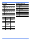
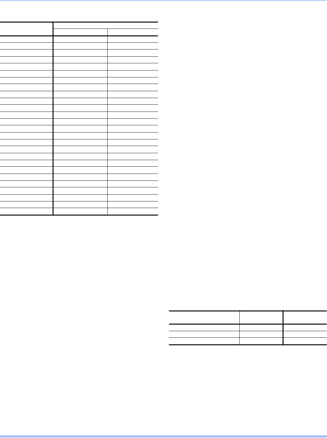
Table 27: Gas Rate Cubic Feet Per Hour
Seconds for
One Rev.
Size of Test Dial
1/2 cu. ft. 1 cu. ft.
10 180 360
12 150 300
14 129 257
16 113 225
18 100 200
20 90 180
22 82 164
24 75 150
26 69 138
28 64 129
30 60 120
32 56 113
34 53 106
36 50 100
38 47 95
40 45 90
42 43 86
44 41 82
46 39 78
48 37 75
50 36 72
52 35 69
54 34 67
56 32 64
58 31 62
60 30 60
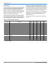
Table 28: Gas Heat Stages
# of Burner Tubes
2nd Stage Input
(100% Btuh)
1st Stage Input
(60% Btuh)
4 120,000 72,000
6 180,000 108,000
8 240,000 144,000