


518676-BIM-E-1210
50 Johnson Controls Unitary Products
Continuous Blower
By setting the room thermostat fan switch to "ON," the supply
air blower will operate continuously.
Intermittent Blower
With the room thermostat fan switch set to "AUTO" and the
system switch set to either the "AUTO" or "HEAT" settings, the
blower is energized whenever a cooling or heating operation is
requested. The blower is energized after any specified delay
associated with the operation.
When energized, the indoor blower has a minimum run time of
30 seconds. Additionally, the indoor blower has a delay of 10
seconds between operations.
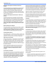
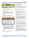
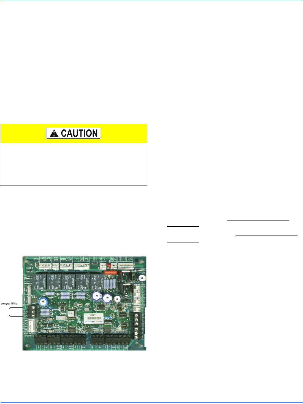
Optional VAV Start-up and Control
For units with VFD and VAV control, the unit must first be put
into the Occupied Mode to start operation. The default setting
for all VAV units is 'Unoccupied', therefore the installer must
add a jumper wire between terminals R - OCC on the VAV add-
on board to put the unit into 'Occupied' Mode. Additionally, the
unit can be switched between Unoccupied/Occupied mode
through network communications with Simplicity™ PC and
other BAS control systems.
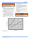
Figure 33: Occupied Jumper
Once placed into the Occupied Mode, the speed of the indoor
blower motor is controlled by duct static pressure. The Duct
Static set point (default = 1.5") is the pressure that the VFD
drive will maintain when operating the unit in VAV mode. If the
duct static pressure reaches or exceeds the high-limit set-point
(default = 4.5"), then the supply fan motor will be shutdown.
The Supply Air Temperature (SAT) is controlled by staging
compressors on and off to satisfy the "Operating Cooling
Supply Air Temp Set point". There are 3 set points that
determine the resulting "Operating Cooling Supply Air Temp
Set point".
1. VAV Cooling Supply Air Temp Upper Set point
(default 60° F)
2. VAV Cooling Supply Air Temp Lower Set point
(default 55° F)
3. VAV Supply Air Temp Reset Set point (default 72° F)
When the Return Air Temp (RAT) is above the "VAV Supply Air
Temp Reset Set point" the SAT will be maintained at +/- 5
degrees of the "VAV Cooling Supply Air Temp Lower Set point".
When the Return Air Temp (RAT) is below the "VAV Supply Air
Temp Reset Set point" the SAT will be maintained at +/- 5
degrees of the "VAV Cooling Supply Air Temp Upper Set point".
When the Outdoor air condition is sufficient for free cooling, the
economizer will modulate to control the SAT to +/- 1 degrees of
the operational set point.
The following components are needed to access the control
points in the Simplicity® controller. Installation and operation
guide is located on UPGNET.
1. Computer running Windows software with a standard USB
port.
2. Simplicity® PC Software (http://www.yorkupg.com/
software.asp)
3. Freenet USB adapter driver, (http://www.yorkupg.com/
software.asp)
4. Simplicity® Freenet USB Adapter (S1-03101967000)
5. Freenet service cable (S1-02538682000)
No Outdoor Air Options
When the thermostat calls for the first stage of cooling, the low-
voltage control circuit from “R” to “Y1” and “G” is completed.
The UCB energizes the economizer (if installed and free cooling
is available) or the first available compressor
*
and the
condenser fans. For first stage cooling, compressor #1 is
energized. If compressor #1 is unavailable, compressor #2 is
energized. After completing the specified fan on delay for
cooling, the UCB will energize the blower motor.
When the thermostat calls for the second stage of cooling, the
low-voltage control circuit from “R” to “Y2” is completed. The
control board energizes the first available compressor. If free
cooling is being used for the first stage of cooling, compressor
#1 is energized. If compressor #1 is active for first stage cooling
or the first compressor is locked-out, compressor #2 is
energized. In free-cooling mode, if the call for the second stage
of cooling continues for 20 minutes, compressor #2 is
energized, provided it has not been locked-out.
If the unit is operated with the optional manual bypass
switch in the LINE (BYPASS) position and there are
VAV boxes present in the duct system, then boxes must
be driven to the full-open position using a customer-
supplied power source to prevent over-pressurizing and
possible damage to the ductwork.