


518676-BIM-E-1210
56 Johnson Controls Unitary Products
The ICB monitors the Pressure and Rollout switches of gas
heat units.
The control circuit includes the following safety controls:
Pressure Switch (PS)
Once the draft motor has reached full speed and closes the
pressure switch during a normal ignition sequence, if the
pressure sw opens for 2 seconds, the GV will be de-energized,
the ignition cycle is aborted, and the ICB flashes the
appropriate code. See Table 31 Ignition Control Flash Codes.
The draft motor is energized until the pressure switch closes or
“W1” is lost.
Rollout Switch (ROS)
The rollout switch is wired in series with the pressure switch. As
such, the ICB cannot distinguish the rollout switch operation
from that of the pressure switch.
Consequently, the control will only respond in the same manner
as outlined above under “Pressure Switch”. An open rollout will
inhibit the gas valve from actuating.
Internal Microprocessor Failure
If the ICB detects an internal failure, it will cease all outputs,
ignore inputs, and display the proper flash code for control
replacement. The ICB remains in this condition until replaced.
Flash Codes
The ICB will initiate a flash code associated with errors within
the system. Refer to IGNITION CONTROL FLASH CODES
Table 31.
Resets
Remove the call for heating by lowering the thermostat setting
lower than the conditioned space temperature. This resets any
flash codes.
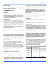
Gas Heat Anticipator Setpoints
It is important that the anticipator setpoint be correct. Too high
of a setting will result in longer heat cycles and a greater
temperature swing in the conditioned space. Reducing the
value below the correct setpoint will give shorter “ON cycles
and may result in the lowering of the temperature within the
conditioned space. Refer to Table 26 for the required gas heat
anticipator setting.
Start-Up (Cooling)
Prestart Check List
After installation has been completed:
1. Check the electrical supply voltage being supplied. Be sure
that it is the same as listed on the unit nameplate.
2. Set the room thermostat to the off position.
3. Turn unit electrical power on.
4. Set the room thermostat fan switch to on.
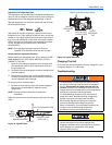
5. Check indoor blower rotation.
• If blower rotation is in the wrong direction. Refer to
Phasing Section in general information section.
Check blower drive belt tension.
6. Check the unit supply air (CFM).
7. Measure evaporator fan motor's amp draw.
8. Set the room thermostat fan switch to off.
9. Turn unit electrical power off.
Operating Instructions
1. Turn unit electrical power on.
NOTE: Prior to each cooling season, the crankcase heaters
must be energized at least 10 hours before the system
is put into operation.
2. Set the room thermostat setting to lower than the room
temperature.
3. First stage compressors will energize after the built-in time
delay (five minutes).
4. The second stage of the thermostat will energize second
stage compressor if needed.
Post Start Check List
1. Verify proper system pressures for both circuits.
2. Measure the temperature drop across the evaporator coil.
Start-Up (Gas Heat)
Pre-Start Check List
Complete the following checks before starting the unit.
1. Check the type of gas being supplied. Be sure that it is the
same as listed on the unit nameplate.
2. Make sure that the vent outlet and combustion air inlet are
free of any debris or obstruction.
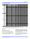
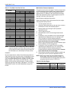
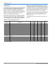
Table 26: Gas Heat Anticipator Setpoints
SETTING, AMPS
W1 W2
0.65 0.1