


518676-BIM-E-1210
36 Johnson Controls Unitary Products
Bas-ready VFD
Factory-installed VFD is also available with 'BAS-Ready'
models. Terminal blocks are provided in the control box (in
place of the VAV control board) for field wiring of a customer-
installed BAS to receive 24 VAC power and to connect to the
following control signals:
• a duct static pressure transducer input signal (0-5 VDC)
• an economizer actuator input signal (2-10 VDC)
• an economizer actuator output signal (2-10 VDC)
• a VFD speed reference output signal (2-10 VDC)
The use of shielded cable is recommended for the above
control wiring connections.
NOTE: Factory-installed VFD is not available with factory-
installed BAS options due to space limitations in the
control box.
A solid-state, lock-out relay (LR) and 100 microfarad, 50 VDC
capacitor must be field-supplied and installed to provide a
means to transmit a potential fault signal back to the BAS
controller. The specific relay part number required will depend
upon the need for either AC-output or DC-output. See price
pages for further details.
Once the appropriate relay and capacitor are obtained, install
the capacitor across LR terminals '3' & '4' and make the
following wiring connections:
• LR '1' to BAS controller
• LR '2' to BAS controller
• LR '3' to UCB 'X'
• LR '4' to UCB 'C'
'VFD-ready' For Customer-installation
Units configured as 'VFD-ready' provide provisions for a
customer-installed drive. The physical dimensions of VFDs can
vary greatly among manufacturers, horsepower ratings and
voltage requirements. Keep in mind that drive manufacturers
also require various minimum clearances to allow for adequate
internal cooling of the drive during operation.
The unit comes with a mounting bracket installed in the Blower
Access compartment which may accommodate other vendor's
drives depending on their size. In order to utilize the unit's
mounting bracket, the maximum recommended drive
dimensions are limited to approximately 9" H x 5" W x 7.5" D.
If the drive will not fit in the allotted space, then it will need to be
mounted elsewhere; either within the building on a
perpendicular wall which is not subjected to excessive
temperature, vibration, humidity, dust, corrosive gas, explosive
gas, etc., or within an appropriate enclosure rated for outside
installation to safeguard against moisture, dust and excessive
heat.
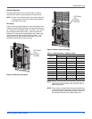
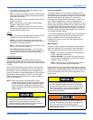
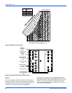
The power leads to the drive (L1, L2, L3) and from the motor
(T1, T2, T3) have been temporarily spliced together with wire
nuts. After removing the wire nuts, connect the wires to the
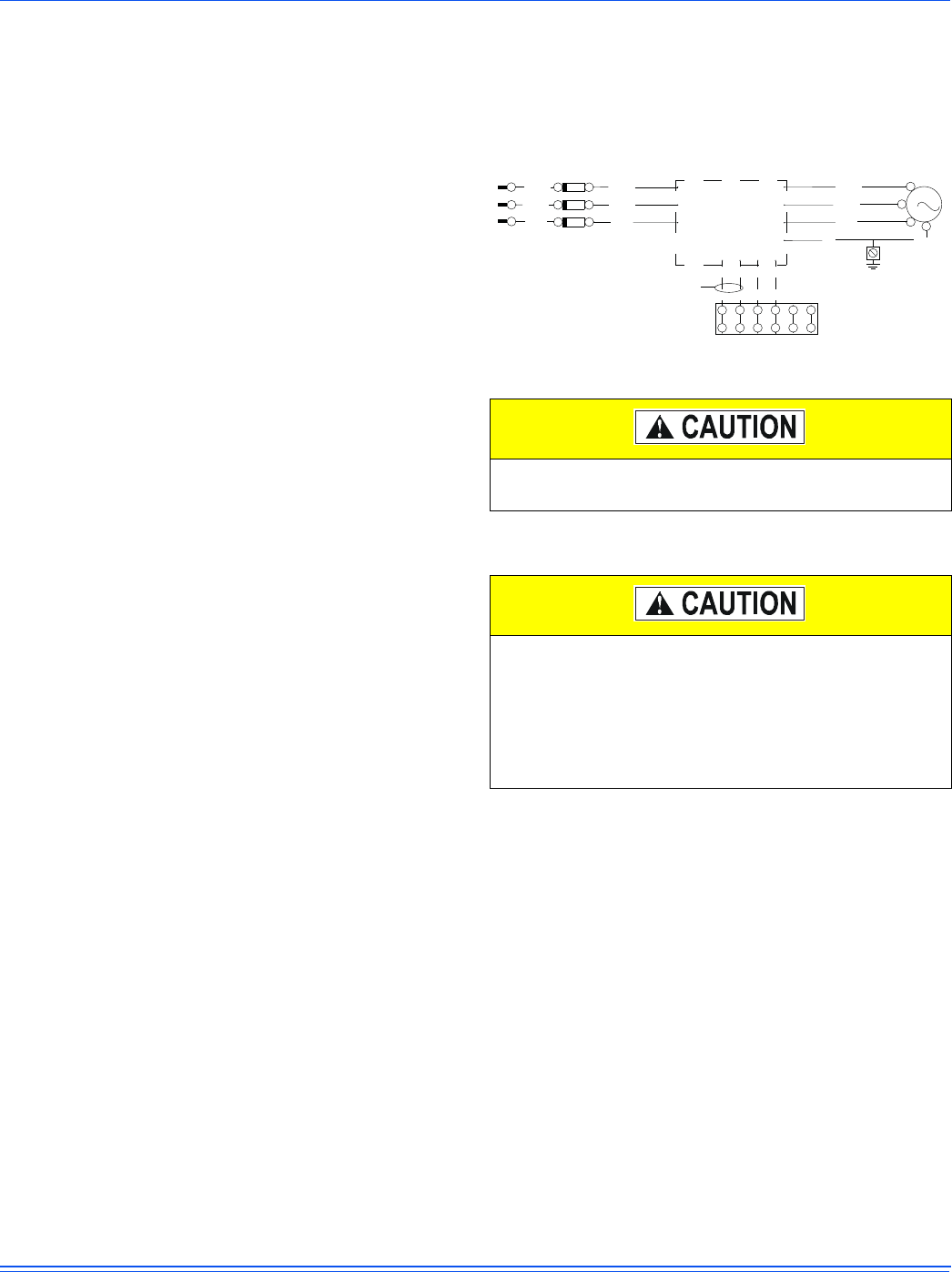
field-installed VFD per the VFD wiring diagram (See Figure 27).
The VFD should also be grounded per the manufacturer's
specifications.
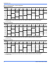
Figure 27: Simplified VFD Wiring
A terminal block located in the control box is provided for field
connection of the VFD speed reference signal (2-10 VDC) and
to the normally-open, run-permit auxiliary contact. The use of
shielded cable is recommended for the above control wiring
connections. For VFD-ready units also equipped with gas/
electric heat, a terminal block located in the unit's control box
and connected to the VAV board's "VAV BOX" terminal, must
be field wired to the building's VAV boxes to ensure fully open
dampers during heating operation.
Optional Hot Gas Bypass (HGBP)
To allow for low cooling load operation, a direct-acting,
pressure-modulating bypass control valve installed on the
system #1 discharge line is used to divert high temperature,
high pressure refrigerant around the TXV in order to maintain a
desired minimum evaporator pressure.
The opening pressure of the bypass valve is adjustable
between 95 and 115 psig with a factory-setting of 105 psig.
Do not connect AC power to the T1, T2, T3 drive
terminals to prevent damage to the VFD.
The fuses (FU3, FU4, FU5) supplied with the unit are
sized according to the electrical load of the blower
motor, but may not provide adequate protection to the
customer-installed drive, depending upon its
specifications. Once a drive has been selected and
installed, refer to the drive manufacturer's
recommendations for proper fuse sizing.
ELEMENTARY DIAGRAM
VFD
TB8 (IN CONTROL BOX)
RUN PERMIT
(DIGITAL)
SPEED REF
(ANALOG)
(2-10 VDC)
GND
GRN
GND
GRN
GND
1 DMTR
118 / BK
119 / BR
120 / Y
3
M
(T1)
(T2)
(T3)
( )
(L1)
(L3)
(L2)
722 / BK
725 / BR
728 / Y
720 / PR
723 / BR
726 / O
TB1
FU3
FU5
FU4
12345
6
L3
L2
L1
T1
T2
T3