


518676-BIM-E-1210
32 Johnson Controls Unitary Products
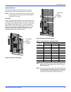
Gas Connection
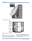
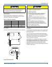
The gas supply line can be routed within the space and roof curb,
exiting through the unit’s basepan. Refer to Figures 8 and 9 for
the gas piping inlet location. Typical supply piping arrangements
are shown in Figures 25 and 26. All pipe nipples, fittings, and the
gas cock are field supplied or may be purchased in UP accessory
kit #1GP0405.
Gas piping recommendations:
1. A drip leg and a ground joint union must be installed in the
gas piping.
2. Where required by local codes, a manual shut-off valve
must be installed outside of the unit.
3. Use wrought iron or steel pipe for all gas lines. Pipe dope
should be applied sparingly to male threads only.
4. All piping should be cleaned of dirt and scale by
hammering on the outside of the pipe and blowing out
loose particles. Before initial start-up, be sure that all gas
lines external to the unit have been purged of air.
5. The gas supply should be a separate line and installed in
accordance with all safety codes as prescribed under
“Limitations”.
6. A 1/8-inch NPT plugged tapping, accessible for test gage
connection, must be installed immediately upstream of the
gas supply connection to the unit.
7. After the gas connections have been completed, open the
main shut-off valve admitting normal gas pressure to the
mains. Check all joints for leaks with soap solution or other
material suitable for the purpose. NEVER USE A FLAME.
LP Units, Tanks And Piping
All gas heat units are shipped from the factory equipped for
natural gas use only. The unit may be converted in the field for
use with LP gas with accessory kit model number 1NP0442.
All LP gas equipment must conform to the safety standards of
the National Fire Protection Association.
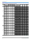
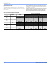
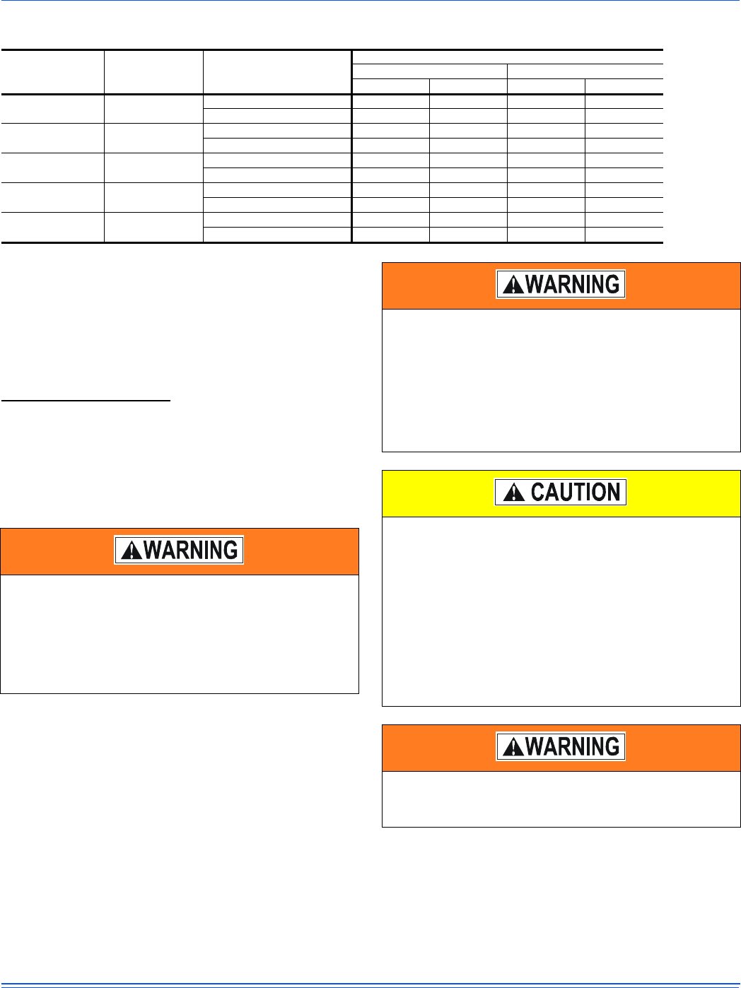
Table 12: Gas Heat Minimum Supply Air
Size
(Tons)
Model Heat Size
Supply Air (CFM)
Cooling Heating
Min Max Min Max
-06
(6.5)
ZS
12 1950 3250 1950 3250
18 1950 3250 1950 3250
-07
(7.5)
ZS
12 2250 3750 2250 3750
18 2250 3750 2250 3750
-08
(8.5)
ZS
12 2550 4250 2550 4250
18 2550 4250 2550 4250
-10
(10)
ZS
18 3000 5000 3000 5000
24 3000 5000 3000 5000
-12
(12.5)
ZS
18 3750 6250 3750 6250
24 3750 6250 3750 6250
Natural gas may contain some propane. Propane is an
excellent solvent and will quickly dissolve white lead and
most standard commercial compounds. A special pipe
dope must be used when assembling wrought iron or
steel pipe. Shellac based compounds such as Gaskolac
or Stalastic, and compounds such as Rectorseal #5,
Clydes’s or John Crane may be used.
FIRE OR EXPLOSION HAZARD
Failure to follow the safety warning exactly could result
in serious injury, death or property damage.
Never test for gas leaks with an open flame. use a
commercially available soap solution made specifically
for the detection of leaks to check all connections. A fire
or explosion may result causing property damage,
personal injury or loss of life.
The furnace and its individual shut-off valve must be
disconnected from the gas supply piping system during
any pressure testing at pressures in excess of 1/2 PSIG.
Pressures greater than 1/2 PSIG will cause gas valve
damage resulting in a hazardous condition. If it is
subjected to a pressure greater than 1/2 PSIG, the gas
valve must be replaced.
The furnace must be isolated from the gas supply piping
system by closing its individual manual shut-off valve
during any pressure testing of the gas supply piping
system at test pressures equal to or less than 1/2 PSIG.
Threaded joints should be coated with a sealing
compound that is resistant to the action of liquefied
petroleum gases. Do not use Teflon tape.