


FORM 145.15-IOM7 (412)
JOHNSON CONTROLS 5
UNIT MOUNTING
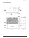
The 5 ~ 20 ton models are shipped as a fully
assembled integral package. If required units may be
field split to allow for passage through doors,
elevators, hallways, etc.
Duct flanges for evaporator return are incorporated
into the filter rack.
Units should be secured on a solid, level pad or sturdy
stand. The use of an isolating rubber sheet is
recommended to reduce vibration and noise
transmission. Ensure that the entire base is
continuously supported - do not support unit at corner
points only! Unit may be pitched slightly to ensure
efficient drainage of condensate.
EVAPORATOR / CONDENSER SEPARATION - (All
models)
- Reclaim the entire refrigerant charge from each
compressor circuit.
- Disconnect the evaporator motor high voltage
wires. Pull all wiring into the evaporator
compartment. Remove bushing/clamp from
routing hole for evaporator motor wiring.
- Cut and remove sections of all liquid and suction
refrigerant lines. Make two cuts in each line,
approximately 6 inches above and below the
evaporator floor/condenser roof.
Use a TUBING CUTTER ONLY - do
not use a hacksaw to cut refrigerant
tubing otherwise serious damage
can occur to refrigeration system!
- Remove corner securing brackets from the
outside corners of the cabinet, at the joint line
between the evaporator and condenser sections.
- Remove the evaporator section.
ASSEMBLY OF SPLIT UNITS - (All models)
- Place the condenser section in the required
location.
- Carefully position the evaporator section atop the
condensing section. Align all sides, the evaporator
motor wire routing hole, and the refrigerant line
routing holes.
- Install the securing brackets at all four corners, on
the evaporator/condenser separation joint. Note
that one bracket, intended for use at the corner
with the +drain fitting, has a short "leg".
- Use appropriate tubing couplings and splice
previously cut refrigerant lines. Pressure test
refrigerant circuits with dry nitrogen (500 psig).
- Evacuate each circuit to at least 350 microns. If
gauge pressure rises above 500 microns in one
minute, evacuation is incomplete or the system
has a leak.
- Charge circuit(s) to the value indicated on the unit
nameplate.
- Install bushing/clamp into evaporator wiring
routing hole, and pull wires through into electrical
control panel. Connect motor leads to load
terminals on contactor/overload relay.
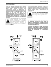
Ensure evaporator motor rotation is
correct upon unit start-up. Switch any
two wires at contactor if blower
rotation is not correct.
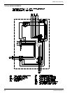
WATER PIPING
All factory installed water piping terminates inside the
unit. Multi-condenser units feature manifolded single
water in and out connections.
Water connection fittings are threaded
copper. Use caution when tightening
steel pipe into copper fittings. Always
use a backing wrench on the hex
fittings inside the unit.
It is recommended that flexible connectors be
provided on the water supply and return lines if noise
and vibration transmission could be a problem.
Water piping should include shutoff / balancing valves
so that the unit can be serviced without shutting down
and draining the entire water supply circuit. Since
units are piped in parallel piping circuits, the shutoff
valves may be used to equalize the pressure drop to
each branch for even condenser water distribution. A
bibcock or a plugged tee fitting should be installed
between the shut-off valves and the unit in both the
inlet and outlet pipes. These connections are to
provide for acid cleaning of the condenser, if this
should become necessary.