


FORM 145.15-IOM7 (412)
JOHNSON CONTROLS 23
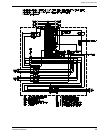
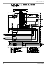
MICROPROCESSOR CONTROLLER
The microprocessor control system is specifically
designed for single and dual stage systems. The
control system interfaces with a conventional type
thermostat.
• Unit shall be complete with self-contained low-
voltage control circuit
• Unit shall incorporate a lockout circuit which
provides reset capability at the space thermostat
or base unit, should any of the following standard
safety devices trip and shut off compressor.
- Loss-of-charge/Low-pressure switch
- High-pressure switch
- Condensate Overflow protection switch
• Unit shall operate with conventional thermostat
designs and have a low voltage terminal strip for
easy hook-up.
• Unit control board shall have on-board diagnostics
and fault code display.
• Standard controls shall include anti-short cycle
and low voltage protection
• Control board shall monitor each compressor and
refrigerant safety switch independently.
• Control board shall have random start feature
• Control board shall retain last 5 fault codes in non
volatile memory which will not be lost in the event
of a power loss.
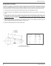
OPERATION
For cooling the room t-stat energizes the low-voltage
circuit between “R” & “Y1”.
The call is passed to the unit microprocessor control,
which then determines whether the requested
operation is available and, if so, which components to
energize.
CONTINUOUS BLOWER
By setting the room t-stat fan switch set to “ON”, the
supply air blower will operate continuously. With the
room t-stat fan switch set to “AUTO”, the blower is
energized whenever a cooling operation is requested.
The blower is energized after any specified delay
associated with the operation.
When energized, the indoor blower has a minimum
run time of 30 seconds. Additionally, the indoor blower
has a delay of 10 seconds between operations.
When the room t-stat calls for cooling, the low-voltage
control circuit from “R” to “Y1”and “G” is completed.
The compressor and fan motor are energized. After
completing the specified fan on delay for cooling, the
microprocessor control will energize the blower motor.
Once the room t-stat has been satisfied, it will de-
energize “Y1”. If the compressor has satisfied its
minimum run time, the compressor and fan de-
energize. Otherwise, the unit operates the cooling
system until the minimum run time for the compressor
has been completed. After the compressor de-
energizes, the blower is stopped following the elapse
of the fan-off delay for cooling.
To be available, a compressor must not be locked-out
due to a high-pressure switch; low- pressure switch;
condensate overflow switch; and the anti-short cycle
delay (ASCD) must have elapsed.
SAFETY SWITCHES
Each refrigerant system is monitored to ensure it does
not operate outside of its intended operating
parameters. Safety switches are handled as described
below. All system errors override minimum run times
for compressors.
High-Pressure Limit Switch
If a high-pressure limit switch opens, the
microprocessor control de-energizes the compressor,
initiates the ASCD, and stops the fan. If a call for
cooling or heating is still present at the conclusion of
the ASCD, the microprocessor control will re-energize
the compressor and unit fan.
Should a high-pressure switch open three times within
two hours of operation, the microprocessor control will
permanently lock-out the compressor. The system
must be manually reset by de-energizing the 24 volt
power to unit, or turning the room t-stat to the “OFF”
position then back to cooling position. The
microprocessor control will flash a fault code
indicating a high-pressure lock-out.
Low-Pressure Limit Switch
The low-pressure limit switch is not monitored during
the initial 30 seconds of compressor operation. After
the initial 30 seconds have passed, the
microprocessor control will monitor the low-pressure
switch for another 30 seconds. If the low-pressure
switch fails to close after the 30 second monitoring
phase, the microprocessor control will de-energize the
compressor, initiate the ASCD, and stop the fan.
Once the low-pressure switch has been proven
(closed during the 30-second monitoring period as