


FORM 145.15-IOM7 (412)
JOHNSON CONTROLS 11
ELECTRICAL WIRING
Follow local electrical codes when making electrical
connections. Units are completely factory wired for
normal supply voltages (ie.208-230, 460,
575V/3Ph/60Hz) Confirm unit specifications by
checking unit data plate. All electrical components are
accessible through an independent electrical panel
located on the right hand end of the
evaporator/compressor section. The electrical control
boxes are located behind outer access panels. The
compressor section electrical cover is provided with
wiring diagrams on the inside, which must be opened
to be read.
DISCONNECT AND LOCK OUT POWER
WHEN SERVICING UNIT. UNIT MAY
START AUTOMATICALLY IF POWER IS
NOT DISCONNECTED. FAILURE TO DO
SO MAY RESULT IN PERSONAL IN-
JURY OR DEATH DUE TO ELECTRICAL
SHOCK.
Provide individual power disconnects for each unit.
Install a secure ground to the bonding lug located in
the electrical control panel. If canvas flexible joints are
used on ductwork, install a ground wire to the
ductwork as well.
All wiring must comply with applicable
local and national codes (NEC). Type
and location of disconnect switches
must comply with all applicable codes.
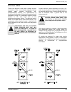
Unit requires installer to provide a 24volt thermostat
with appropriate heating and cooling stages as
needed. For low voltage wiring, 18 gauge wire may be
used for up to 50 feet lengths. Low voltage runs up to
125 feet require 16 gauge wire.
All models are designed for single zone cooling
applications, utilizing space or return air thermostatic
controls. A low voltage terminal block is provided for
hook-up of conventional or programmable
thermostats.