


FORM 145.15-IOM7 (412)
10 JOHNSON CONTROLS
DUCTWORK
When installing ductwork, adhere to local Codes and
sensible practice. Minimize duct runs and avoid abrupt
changes in direction where possible. Allow ample
access space for servicing of the coils and changing
of filters. Perform regular maintenance on ducts to
increase unit life, maintain efficient operation, and
reduce accumulation of explosive dust. Refer to
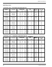
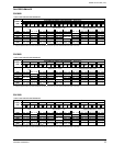
blower performance charts, and engineer duct runs
and accessory pressure drop so as not to exceed
maximum external static values.
Canvas or other types of flexible collars are
recommended for connecting the air ducts to the unit.
The supply air duct collar can be connected directly to
the blower outlet flanges. Return air may be ducted to
the unit, or drawn directly from the conditioned space
(with optional return air grille). If a ducted return is
desired, duct connection flanges may be secured
directly to the air intake opening – filters are
accessible from the right hand side.
The Manufacturer will not accept any
liability resulting from incorrect instal-
lation of this equipment. Follow instal-
lation instructions carefully.
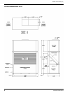
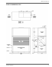
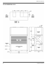
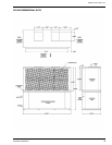
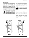
EVAPORATOR BLOWER DISCHARGE
CONVERSION
All models can be field converted to the alternate
evaporator discharge orientation, as indicated on the
unit dimensional drawings. All models are shipped
with vertical fan discharge as standard.
The removable upper fan module that can be rotated
180°
for top rear discharge applications (see below). In
addition, the blower outlet panel may be interchanged
with the front panel of the fan module. Interchanging
these two panels allows horizontal fan discharge to
either front or rear of the unit.
Procedure for converting the fan discharge from
vertical to horizontal is similar on all models, single fan
or dual fan.
- Remove blower drive belt on all models with base
mounted motors. Remove the complete fan motor
and drive on models with blower mounted motor
assemblies.
- Remove the panel attachment screws on the
alternate location access panel (front blower
module panel). The front roof support angle must
be removed to allow access to the front panel.
Remove the panel and set aside.
- Remove the panel attachments screws on the
blower outlet mounting panel. Do not remove
fasteners securing blowers to panel! The blowers
are to remain attached to the mounting panel at all
times.
- Carefully remove the blower panel assembly from
the evaporator cabinet. Do not allow blower
housings to contact the evaporator coil during the
removal. On some models, the housing(s) will
have to be "rotated" to exit through the panel
opening.
- Interchange the blower panel assembly with the
position of the alternate access panel. Exercise
care in locating the panel. Do not allow blower
housings to contact the evaporator coil. Install the
attachment screws and tighten securely.
- Install the blank access panel into the remaining
evaporator opening. Fasten securely.
- Relocate the evaporator fan drive motor to the
alternate location.
- Install and adjust drive belts to appropriate
tension. Test run blower and observe operation
for unusual sounds or vibration.
In order to utilize the ‘rear vertical’ or ‘rear horizontal’
discharge, the upper fan module must be rotated.
- Disconnect power wiring at motor terminal box.
DISCONNECT AND LOCK OUT
POWER WHEN SERVICING UNIT.
FAILURE TO DO SO MAY RESULT IN
PERSONAL INJURY OR DEATH DUE
TO ELECTRICAL SHOCK.
- Remove corner connecting brackets which secure
the blower module to the lower evaporator unit.
- Carefully lift the blower module, and rotate 180
0
.
Reposition the blower module on top of the
evaporator/compressor unit. Reinstall the corner
connecting brackets.
Connect new power wire leads, from the evaporator
motor contactor in the electrical box to the motor
terminal box. Ensure wires are routed clear of any
moving components. Secure the wiring so that it does
not contact the evaporator coil.