


Intel ATX Power Supply Design Guide
Version 0.9
Page 24
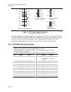
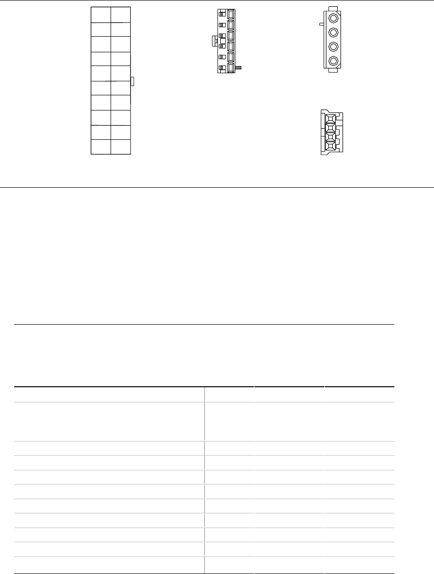
+3.3VDC
COM
+5VDC
COM
+5VDC
COM
PWR_OK
+5VSB
+12VDC
+3.3VDC
-12VDC
COM
PS_ON#
COM
COM
COM
-5VDC
+5VDC
+5VDC
Pin 11
Pin 1
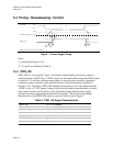
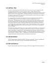
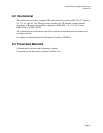
ATX Main Power Connector
COM
COM
COM
+3.3VDC
+3.3VDC
+5VDC
Aux Power
Pin 1
Pin 6
(250 W & 300 W Systems)
Connector
+12VDC
COM
COM
+5VDC
Peripheral Power
Connector
Floppy Drive
Power Connector
+5VDC
COM
COM
+12VDC
Pin 1
Pin 4
Pin 1
Pin 4
+3.3VDC
Figure 4: ATX Power Supply Connectors
(Pin-side view, not to scale)
Listed or recognized component appliance wiring material (AVLV2), CN, rated min 85 °C,
300 VDC shall be used for all output wiring. There are no specific requirements for length
or color of wiring from the power supply. The following sections suggest wire color
coding that is followed by many vendors, but this color coding is NOT required.
4.5.1 ATX Main Power Connector
Connector: MOLEX 39-01-2200 or equivalent
(Mating motherboard connector is Molex 39-29-9202 or equivalent)
18 AWG is suggested for all wires except for the +3.3 V supply and sense return wires
combined into pin 11 (22 AWG).
For 300 W configurations, 16 AWG is recommended for all +5VDC, +3.3VDC, and COM.
Pin Signal Color Pin Signal Color
1 +3.3VDC Orange 11
[11]
+3.3VDC
[+3.3 V default
sense]
Orange
[Brown]
2 +3.3VDC Orange 12 -12VDC Blue
3 COM Black 13 COM Black
4 +5VDC Red 14 PS_ON# Green
5 COM Black 15 COM Black
6 +5VDC Red 16 COM Black
7 COM Black 17 COM Black
8 PWR_OK Gray 18 -5VDC White
9 +5VSB Purple 19 +5VDC Red
10 +12VDC Yellow 20 +5VDC Red