


Intel ATX Power Supply Design Guide
Version 0.9
Page 14
3.3.3 Output Ripple/Noise
The following output ripple/noise requirements should be met throughout the load ranges
specified in Section 3.3, and under all input voltage conditions as specified in Section 3.1.
Ripple and noise are defined as periodic or random signals over a frequency band of 10 Hz
to 20 MHz. Measurements shall be made with an oscilloscope with 20 MHz bandwidth.
Outputs should be bypassed at the connector with a 0.1 µF ceramic disk capacitor and a
10 µF electrolytic capacitor to simulate system loading.
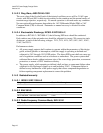
Table 8: DC Output Noise/Ripple
Output Max Ripple & Noise
(mV
pp
)
+12VDC 120
+5VDC 50
+3.3VDC 50
-5VDC 100
-12VDC 120
+5VSB 50
3.3.4 Output Transient Response
The +3.3VDC and +5VDC outputs will see transients up to 30% of the rated output current
(e.g., for a rated +5VDC output of 18 A, the transient step would be 0.3 × 18 A = 5.4 A).
The +12VDC output will see transients up to 50% of the rated output current. The transient
slew rate will be 2.5 A/µs. The power supply should be stable under all transient
conditions from any steady state load, and the over/undershoot should be within the
regulation band stated in Section 3.2.1.
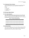
3.3.5 Capacitive Load
The power supply should be able to power up and operate normally with the following
capacitances simultaneously present on the DC outputs.
Output: +12VDC +5VDC +3.3VDC -5VDC -12VDC +5VSB
Capacitive load (µF):
1,000 10,000 6,000 350 350 350
3.3.6 Closed Loop Stability
The power supply shall be unconditionally stable under all line/load/transient load
conditions including capacitive loads specified in Section 3.3.5. A minimum of 45 degrees
phase and 10 dB-gain margin is required. The power supply vendor shall provide proof of
the unit’s closed-loop stability with local sensing through the submission of Bode plots.
Closed-loop stability must be ensured at the maximum and minimum loads as applicable.