Intel ATX Power Supply Design Guide
Version 0.9
Page 23
4.3 Airflow / Fan
In general, exhausting warm air from the chassis enclosure via a power supply fan at the
rear panel is the preferred system-level airflow solution. Other solutions may be
implemented, however, and some system/chassis designers may reverse this airflow to meet
specific system cooling requirements. Ultimately, the choice of fan location and direction
for a power supply in an ATX system must yield acceptable cooling for the power supply
and all integrated chassis components.
It is suggested that an 80 mm ball bearing fan be used in conjunction with a thermally
sensitive fan speed control circuit to balance system-level thermal and acoustic
performance. The thermal fan speed control typically should sense the temperature of the
secondary heatsink and/or incoming ambient air and adjust the fan speed as necessary to
keep power supply and system component temperatures within specification. Both the
power supply and system designer should be aware of the dependencies of the system and
power supply temperatures on the control circuit response curve and fan size and specify
them accordingly.
The intake and exhaust grills of the power supply should remain suitably free of obstruction
so as not to hinder airflow or generate excessive acoustic noise (i.e. no objects within 0.5
inches of the intake or exhaust areas). The opening must be sufficiently protected to meet
the safety requirements described in Section 8. For the grill pattern area relevant to a given
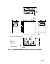
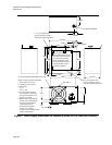
chassis design, see Figures 2 and 3. A flush mount wire fan grill can be used instead of a
stamped metal grill to maximize airflow and minimize acoustic noise.
4.4 AC Connector
The AC input receptacle should be an IEC 320 type or equivalent. In lieu of an additional
switch, the IEC 320 receptacle may be considered the mains disconnect.
4.5 DC Connectors
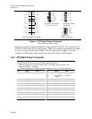
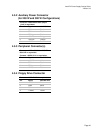
Figure 4 shows pinouts and profiles for typical ATX power supply DC harness connectors.


