


Intel ATX Power Supply Design Guide
Version 0.9
Page 16
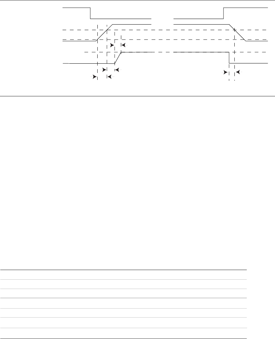
3.4 Timing / Housekeeping / Control
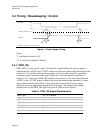
PS_ON#
+5VDC/+3.3VDC O/P
PWR_OK
PWR_OK Sense Level = 95% of nominal
Off
On
95%
10%
~
~
~
T2
T3
T5
T4
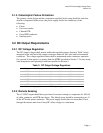
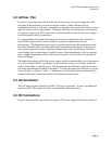
Figure 1: Power Supply Timing
Notes:
T
2
is defined in Section 3.4.5.
T
3
, T
4
, and T
5
are defined in Table 9.
3.4.1 PWR_OK
PWR_OK is a “power good” signal. It should be asserted high by the power supply to
indicate that the +5VDC and +3.3VDC outputs are above the undervoltage thresholds listed
in Section 3.2.1 and that sufficient mains energy is stored by the converter to guarantee
continuous power operation within specification for at least the duration specified in
Section 3.3.8. Conversely, PWR_OK should be deasserted to a low state when either the
+5VDC or the +3.3VDC output voltages falls below the undervoltage threshold, or when
mains power has been removed for a time sufficiently long such that power supply
operation cannot be guaranteed beyond the hold-up time. The electrical and timing
characteristics of the PWR_OK signal are given in Table 9 and in Figure 1.
Table 9: PWR_OK Signal Characteristics
Signal Type +5 V TTL compatible
Logic level low < 0.4 V while sinking 4 mA
Logic level high Between 2.4 VDC and 5 VDC output while sourcing 200 µA
High state output impedance
1K
Ω from output to common
PWR_OK delay 100 ms < T
3
< 500 ms
PWR_OK rise time
T
5
≤ 10 ms
Power down warning T
4
> 1 ms