


OnLine Power
(6002-1646) REV.X8 2
systems, from electrical interference. The Fire Alarm Back-up UPS1481 protects these systems
from power problems associated with poor quality AC power including complete power Outages.
Electrical disturbances can come from practically anywhere: from the incoming power lines and
even from within a building. Outside electrical disturbances include lightning strikes, utility
switching, brown—outs, and accidents. Electrical disturbances from within a building can be
caused by load cycling (elevators, HVAC systems), fault conditions, welders, and other
electrically noisy equipment. Whether the electrical disturbances are generated outside or from
within the facility, the following power problems will occur:
1-3 PRODUCT FEATURES
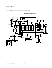
The following describes the major blocks within the Fire Alarm Back-up UPS1481. Please refer
to Illustration. Block Diagram for additional information.
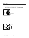
Bypass Static Switch — The SCR solid state switch bypasses the complete UPS and provides
utility input directly to the load in case of problem with UPS. This switch also supplies input
power to the load during the start up. It is connected on the primary side of the optional output
isolation Transformer, when used. This switch maintains it’s status opposite of that of the output
SCR solid state switch.
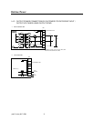
Output Static Switch — This SCR solid state switch connects the output of the inverter (UPS)
to the load. It is connected on the primary side of the optional output isolation transformer, when
used. This switch shuts—off in case of a problem or failure within the UPS and transfers the
load directly to the utility input via bypass static switch. It maintains it’s status opposite to that of
bypass switch.
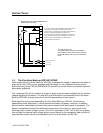
Power Board with IGBTs — The Power board is bolted onto the IGBT blocks that are mounted
on a heat sink. The complete heat sink assembly with IGBT and power board is replaceable as
one part. This assembly processes ail the power, ie. input AC power converted to DC bus,
battery power boosted to DC bus and finally DC bus power converted to output AC power using
PWM technology for smooth AC Sinewave. The complete heat sink assembly is easily
replaceable using only a screwdriver, in case of a catastrophic failure, if required. This board
also has the housekeeping power supplies and driver circuits for IGBTs. This board also
provides the landing place for all internal input, output, and DC cables as well as it monitors the
input-output current for control and metering.
Control Board — The microprocessor with programmable logic controllers and on board
memory is located on this board. It is mounted on the door and communicates, controls, and
monitors the power board via a ribbon cable. This board also senses the input AC and sends
the command to close/open the input contactor, bypass static switch and output static switch.
This board also sends all the data to the LCD display panel located on the door. It also has
modem, AS400, RS232, and RS485 output capabilities.
LCD Display Panel — This front panel provides all the metering data for input, output and
battery; alarm data and UPS status for customer use in a constantly changing and updating, the
3 sets of the screens.