


OnLine Power
(6002-1646) REV.X8 20
3-2-2 Turning off the Fire Alarm Back-up UPS1481 :
1. Turn off the Output Breaker(s), if provided.
2. Turn off the Battery Breaker.
3. Turn off the Input Breaker, if provided.
3-3 Theory of Operation
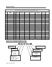
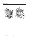
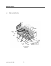
Illustration NO TAG is a simplified block diagram of the Fire Alarm Back-up UPS1481. This
diagram provides an excellent tool in identifying the major building blocks within the Fire
Alarm Back-up UPS1481 .
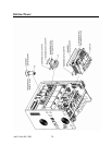
1. External Main input circuit breaker (CB2) — The main input circuit power provides
overcurrent protection to the input side of the Fire Alarm Back-up UPS1481 .
2. Input Contactor (KI) — The microprocessor based control circuitry:
• Verifies UPS to be normal condition and not the one ‘at fault”.
• Verifies correct input voltage and frequency to be within acceptable range and
commands the closure of this. Contactor via control transformer T2 and fuse Fl.
3. Input Chokes (LI, U) — They act as a filter and an important circuitry of an up chopper,
boosting input voltage to a higher internal DC bus voltage.
4. Battery charger — The battery charger converts AC power into regulated DC power to
charge and to maintain the charge on the battery bank. The charger is fully automatic with
a current limiting feature so that damage will not occur to the batteries in case of a charger
malfunction. The charger is sized such that the batteries will be maintained at full charge
even when the input voltage is at the low line limit for indefinite periods of time.
5. Battery — The battery bank, consisting of eight (8), ten (10), sixteen (16), or twenty (20),
12 volt, VRLA batteries, provides the reserve energy to power the load when suitable AC
input power is not present. The batteries are sealed, maintenance—free construction.
6. Inverter — When the AC input power is not available to power the load, the inverter
converts the energy stored in the battery bank to AC power to supply the powers the load.
The pulse width modulated (PWM) inverter utilizes high speed, high efficiency IGBT5 for
fast response, sinusoidal power.
7. DC Choke (U) — If helps boosting battery voltage to an internal higher DC bus voltage.
8. Output AC Choke (L4) — This acts as a buck circuit component connecting high DC bus
voltage to an appropriate AC output voltage.