


OnLine Power
(6002-1646) REV.X8 15
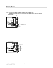
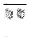
1. Verify that the main input circuit breaker, battery circuit breaker, and output circuit
breaker(s), if provided are in the “OFF” position. See illustration 1-2 for the locations of the
circuit breakers. See under Section 2-5, Storage for accessing the inside of the unit.
2. Run the power wires up through the center area of the Fire Alarm Back-up UPS1481.
Exercise care when working around the battery area.
3. Refer to Section 1-4 for various different installation configurations.
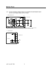
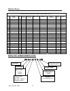
4. Connect the input wires to the input terminal block, TB1. Three (3) wires total: “hot”, neutral
(or Hot), and ground.
5. Connect the output wires to the output terminal block, TB2. Three (3) wires total: “hot”,
neutral (or Hot), and ground to the appropriate designate locations.
6. Connect the battery wires from external battery cabinet (if provided) to battery terminal
block, TB3, three (3) wires total for (+), (-) and Ground.
7. This concludes the electrical connections. Do not apply power to the Fire Alarm Back-up
UPS1481 at this time.
2-3-1 Remote Signaling Connections (AS400)
The Fire Alarm Back-up UPS1481 includes the feature of providing dry relay contacts for remote
signaling capabilities. Signals available of remote annunciation are:
“UTILITY FAILURE” — This is a normally open contact which closes upon loss of input power
to the Fire Alarm Back-up UPS1481 . “LOW BATTERY” — This is a normally open contact
which closes when the Fire Alarm Back-up UPS1481 is on battery operation and the batteries
are approaching complete discharge.
“ON INVERTER or ON BYPASS” — This is a normally open contact which closes when the
Fire Alarm Back-up UPS1481 goes to battery operation.
“SUMMARY ALARM” — This is a normally open contact which closed when the Fire Alarm
Back-up UPS1481 has any one of the alarm condition.
If there are no requirements for remote signaling, section 2-4-1 may be skipped.
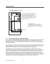
1. The dry relay contacts for remote signaling are provided on connector (P5) of control board
(A2) located on the right door inside of the Fire Alarm Back-up UPS1481. See illustration 1-
2 for exact locations.
2. The dry relay contacts have the following maximum ratings:
200V (AC or DC) maximum
1.25 amperes maximum
30 watts /50 VA maximum, Power Factor 1.0PF
It is imperative that the relay contact ratings are not exceeded. Otherwise, damage to the
relays within the Fire Alarm Back-up UPS1481 will occur.