


Step 10: Install Glass Globe
A.
Before installing the globe, determine which of the (2) pull
chains is used to control the fan. Located on the bottom of the
light fixture, next to the fan pull chain switch is a label marked
Òfan.Ó After installing the globe, pull this chain to control the
fan. Pull the other chain to control the light. After the globe and
finial have been installed, attach the wood balls with the exten-
sion chains to the ends of the fan and light pull chains using the
breakaway connector attached to the end of the extension chains.
See Figure 10C.
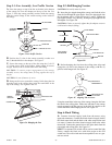
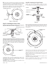
B. Locate the (3) pins at the bottom of the (3) flanges on the
plastic spacer. See Figure 10.
Align the (3) pins with the (3) small clearance holes in the metal
plate at the bottom of the globe assembly. See Figure 10A. Make
certain the (2) pull chains are aligned with the (2) larger out-
board holes in the metal plate.
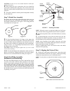
Guide the threaded tube and both chains through the larger holes in
the metal plate. See Figure 10A. Lift the globe until the metal plate
in the bottom of the globe bottoms out against the plastic spacer
with the (3) pins sticking through the small holes in the metal plate.
Keeping the globe in position, place the large flat washer over the
threaded tube and against the bottom of the globe. Thread the assem-
bly nut onto the threaded tube, running it up tight against the bottom
of the washer. Tighten the nut very securely. See Figure 10A.
NOTE: Check and make certain the metal plate in the bottom of
the globe is tight against the plastic spacer.
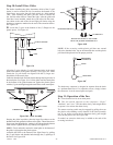
Assemble the finial to the bottom of the light fixture by guiding
the (2) pull chains and threaded tube through the (3) openings in
the finial. See Figure 10B.
NOTE: If the reversing switch plastic pull does not extend
below the threaded tube, tap on the threaded tube and the plastic
pull should drop down into the proper position.
The breakaway connector is designed to separate from the chain
at a predetermined force. If a separation occurs, simply reinsert
the connector. It can be reused again and again.
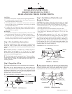
Step 11: Operation of the Fan
A.
Turn electrical service on at main panel.
B. The fan switch operates in this sequence: ÒHigh,Ó
ÒMedium,Ó and ÒLow.Ó Pull the chain slowly and straight down
to operate. Also release the chain slowly.
The motor reversing switch may be engaged by pulling down on
the plastic rod extending out the bottom of the finial assembly
nut. If you wish to reverse the fan direction slowly pull straight
down on the plastic rod. See Figure 10B.
If needed, an extension chain may be added to the end of the
reversing switch rod.
41225-01 10/95 - 6 - ©1995 HUNTER FAN CO.™
Figure 10
Figure 10B
Figure 10C
PLASTIC SPACER
FINIAL
REVERSING SWITCH
CHAIN
BREAKAWAY
CONNECTOR
(8) SIDED NUT
FLANGE
PINS
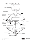
Figure 10A. Globe Assembly
METAL
PLATE
THREADED NUT
WASHER
PULL CHAIN
SECURE THE FINIAL TO THE GLOBE
WITH THE (8) SIDED THREADED NUT.
WOOD BALL