


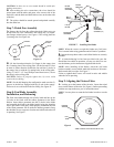
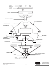

Step 4A. Assemble Top Housing
CAUTION: Do not lift motor by wires.
A. Assemble the housing to the hanger adapter using (3) #8-32
screws. See Figures 4C and 4D. First align the (3) raised tabs of
the hanger adaptor with the (3) narrow notches in the housing.
Make certain the housing sits flat on top of the adaptor. Tighten
the screws securely.
NOTE: Assembly Methods For
InstallerÕs Choice Hanging System
Your new Hunter fan can be hung in (2) different manners. (1) as
a low profile fan or (2) as a ball type hanging fan. Please read
Steps 5 through 7 and decide which style mounting to use.
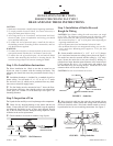
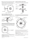
Step 4: Installation of Ceiling Plate
A.
Install the (3) rubber bushings into the top of the ceiling
plate by inserting small side of the rubber bushing into the three
holes in the ceiling plate. See Figure 4.
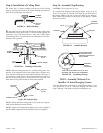
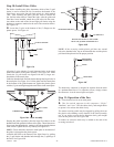
B. Insert the lead wires through the opening in the ceiling plate
and install the ceiling plate to the 2 x 4 brace which supports the
outlet box. Use (2) #10 wood screws 3" long and (2) flat washers
for mounting. Drill (2) pilot holes for the mounting screws 9/64"
diameter. See Figure 4A.
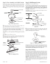
NOTE: When mounting the fan on a vaulted ceiling, make sure
that one set of elongated slots in the ceiling plate is aligned verti-
cally with the ceiling joist, or horizontally with the cross brace if
a cross brace is used. Be sure one of the threaded screw holes in
the side of the ceiling plate is facing down. See Figure 4B. The
hook in the ceiling plate should be in the down position.
NOTE: When attaching ceiling plate to the outlet box support,
make certain bushings remain in place.
NOTE: Tighten the ceiling plate mounting screws only enough to
provide slight compression of the bushings. Do not overtighten.
41225-01 10/95 - 2 - ©1995 HUNTER FAN CO.™
FIGURE 4. Rubber Bushings
FIGURE 4C. Assemble Housing
RUBBER
BUSHING
CEILING
PLATE
FIGURE 4A. Installing Ceiling Plate
RUBBER
BUSHING
CEILING
PLATE
FLAT
WASH-
3" WOOD SCREW
VIEW: LOOKING DOWN ON TOP OF FAN
SHOWING TAB AND NOTCH ALIGNMENT
FIGURE 4D. Assembling Housing
ALIGN RAISED TABS
ON ADAPTOR WITH
NARROW NOTCHES ON
TOP HOUSING
ASSEMBLY
SCREW
LOCATIONS
CEILING
PLATE
HOOK
SCREW HOLE
VAULTED
CEILING
Figure 4B. Vaulted Ceiling
HANGER
ADAPTOR
MOTOR
HOUSING
#8-32