


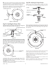
Step 5-1: Fan Assembly, Low Profile Version
A.
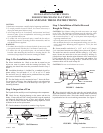
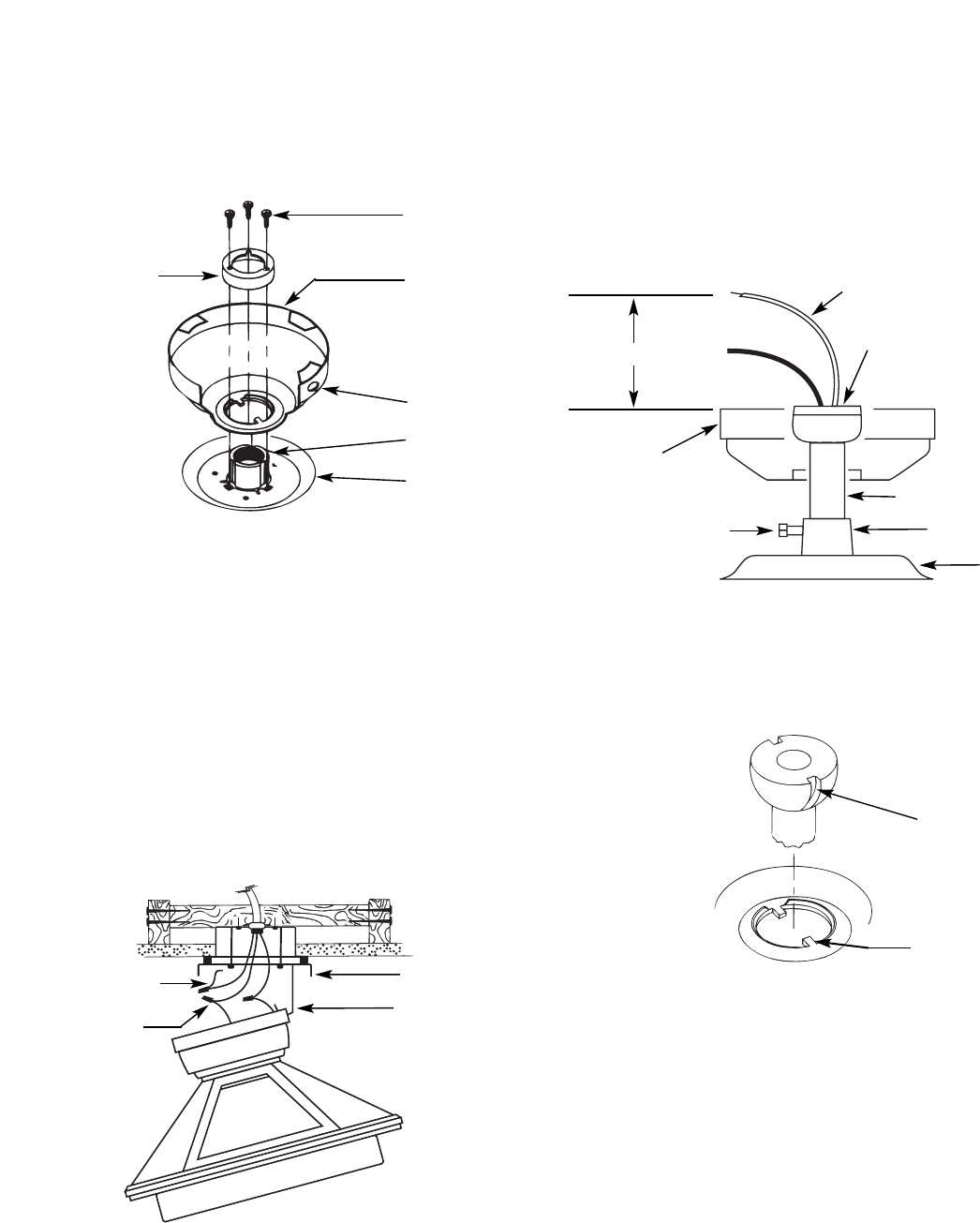
Place the canopy on top of the fan so the hole in the bottom
of the canopy fits over the adaptor on the top of the fan. See
Figure 5. Place the canopy assembly washer inside the canopy
with the vertical flange of the washer resting on the inside of
the canopy.
B. Position the (3) slots in the canopy assembly washer over
the (3) threaded holes in the adaptor. see Figure 5.
C. Secure the canopy to the top of the fan using the (3) #8-32
x 7/8 long screws with lock washers. Make certain all screws
ae tight. Failure to do so could result in the fan falling.
CAUTION: To ensure proper engagement of the canopy
assembly screws, the canopy must fit snug against the top of
the fan.
CAUTION: Do not lift motor by wires.
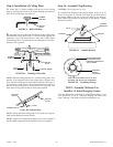
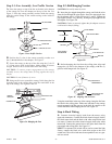
D. Being careful not to scratch the canopy finish, hang the fan
from the hook in the ceiling plate using the round hole in the
top of the canopy. See Figures 5 and 5A.
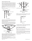
Step 5-2: Ball Hanging Version
CAUTION: Do not lift motor by wires.
A. Insert the pipe nipple through the canopy and feed the wires
from the fan through the pipe nipple. Screw the pipe nipple into
the fan adaptor until it is tight (at least 4-1/2 turns). Tighten the
pipe nipple setscrew very securely, locking the pipe nipple to the
fan adaptor. See Figure 5B.
CAUTION: Failure to securely tighten the fan adaptor setscrew
could result in the fan falling.
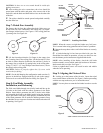
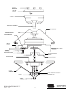
B. Before hanging the fan from the ceiling plate align and
engage the (2) tabs in the bottom of the canopy with the (2)
grooves in the hanger ball. See Figure 5C.
Using the round hole in the top of the canopy, hang the fan from
the hook in the ceiling plate. Make sure both tabs in the canopy
remain engaged with the grooves in the ball. Be careful to not
scratch the finish while hanging the fan. See Figure 5A.
Step 6: Final Wiring
A.
Connect electrical supply leads from the motor, using
approved connectors. Connect the black electrical supply lead to
the black motor lead and the black with white stripe motor lead
(see note). Connect the white electrical supply lead to the white
motor lead. Connect the ground wire to the green leads from the
pipe nipple and ceiling plate. See Figure 5A.
NOTE: If a separate wall switch will be used to control the light
fixture, connect the black wire with white stripe to the wall
switch lead. The wall switch must be acceptable for use as a gen-
eral use switch.
41225-01 10/95 - 3 - ©1995 HUNTER FAN CO.™
Figure 5. Low Profile Version
Figure 5B
ASSEMBLY
WASHER
#8-32 SCREW
CANOPY
ROUND HOLE
LEAD WIRES
PIPE NIPPLE BALL
PIPE NIPPLE
FAN ADAPTOR
MOTOR
PIPE NIPPLE
SETSCREW
CANOPY
ADAPTOR
TOP OF FAN
Figure 5A. Hanging the Fan
GREEN
GROUND
CONNECTOR
CEILING PLATE
HOOK
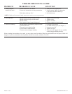
Figure 5C. Aligning Tab & Groove
GROOVE IN
HANGER BALL
TAB IN BOTTOM
OF CANOPY
6" MINIMUM