


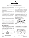
CAUTION: No bare wire or wire strands should be visible after
making connections.
B. After making the wire connections, the wires should be
spread apart with the white and green wires on one side of the
outlet box, and the black and black/white wires on the other side
of the box.
C. The splices should be turned upward and pushed carefully
into the outlet box.
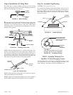
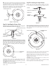
Step 7: Finish Fan Assembly
A.
Remove the fan from the ceiling plate hook. Make sure you
do not break any wire connections. The canopy has (3) suspen-
sion flanges located on top. See Figure 6. The ceiling plate has
(3) mating slots. See Figure 6A.
B. Lift the fan and position the (3) flanges in the canopy into
the (3) mating slots in the ceiling plate. Lift the fan until it is free
to rotate in either direction. Rotate the fan until the (3) holes in
the canopy line up with the (3) mating holes in the ceiling plate.
Using (3) 10-32 x 1/2'' long Phillips round head screws, secure
the canopy to the ceiling plate.
CAUTION: Failure to properly tighten the (3) screws could
result in the fan falling.
NOTE: For the ball hanging fan configuration make sure the (2)
grooves in the ball are engaged with the (2) tabs in the canopy.
Failure to do so could result in the fan falling. See Figure 5C.
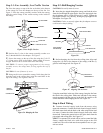
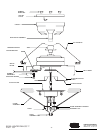
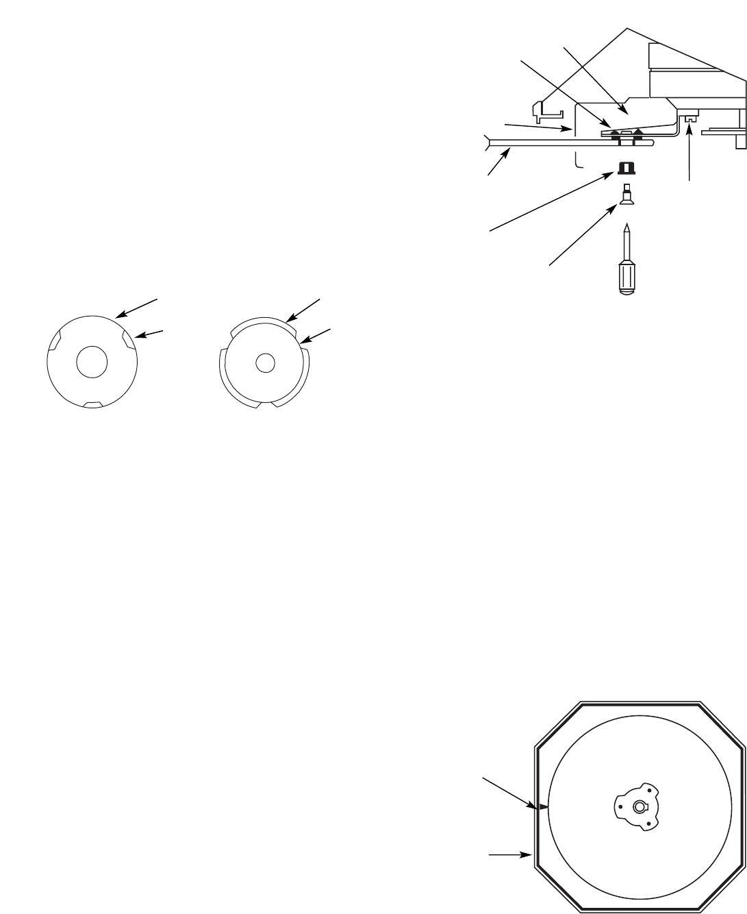
Step 8: Fan Blade Assembly,
Installation, and Balancing
A.
Slide wood blade through slot in belly band and line up the
(2) holes in the blade with the rubber grommets in the blade
bracket. Insert rubber grommets into the (2) holes in the blade
and assemble the blade to the blade bracket using the shoulder
screws provided in sack parts. When properly assembled, the end
of the blade grommets will fit inside the bracket grommet. Snug
the shoulder screws to prevent vibration and wobble when the fan
is operating. See Figure 7.
NOTE: When the screws are tight the blades may feel loose.
This is normal when using grommets and will not be a problem.
B. Repeat the step shown above until all the blades are securely
attached.
C. A blade balancing kit has been provided with your fan.
Should the fan wobble in operation, you may use this kit to cor-
rect the balance per the instructions supplied with the kit.
NOTE: After installing all the blades, check the (10) blade
bracket assembly screws which attach the brackets to the motor.
Make certain they are tight. See Figure 7.
Failure to tighten these screws will result in noise and wobble
when the fan is operating.
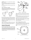
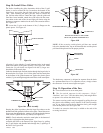
Step 9: Aligning the Fixture Fitter
A.
Looking up at the bottom of the fan trim. Locate the raised
arrow on the bottom of the trim. See Figure 8. Before proceeding
with the next step make sure youÕve located the arrow.
NOTE: You may have to rotate the fan blades in order to see the
arrow.
41225-01 10/95 - 4 - ©1995 HUNTER FAN CO.™
FIGURE 7. Installing Fan Blades
BLADE
BRACKET
GROMMET
RAISED
ARROW
FAN
TRIM
BELLY
BAND
FAN
BLADE
BLADE
GROMMET
SHOULDER
SCREW
BLADE
BRACKET
ASSEMBLY
SCREWS (10)
BLADE
BRACKET
MOTOR
CANOPY
CEILING
PLATE
SLOT
FLANGE
Figure 6 Figure 6A
Figure 8
VIEW LOOKING UP AT BOTTOM OF FAN