


-
7
-
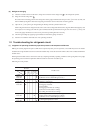
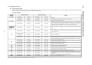
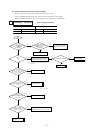
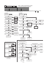
4) Recording and reset of error
Notes (1) Priority is in the order of E1 > ... > E10 > ... > E60.
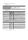
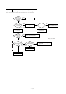
(2) Procedures of trouble diagnosis
When any error occurs, inspect in following sequence. Detailed explanation on each step is given later in this text.
Note (1) It means the operation to turn off the power and back on again more than 1 min. later in order to reset the malfunction of microcomputer due to the
effect of power supply conditions or accidental noise.
Error display Memory Reset
Error code of remote
controller
Indoor unit inspection lamp
(red)
• Saves in memory the mode
(1)
of higher
priority
• Stop the unit operation by pressing the ON/OFF switch of remote
controller.
• Operation can be started again if the error has been reset.
• Saves in memory the mode
(1)
of higher
priority
• Cannot save in memory
Outdoor unit inspection lamp
(red)
Error Power supply reset
(1)
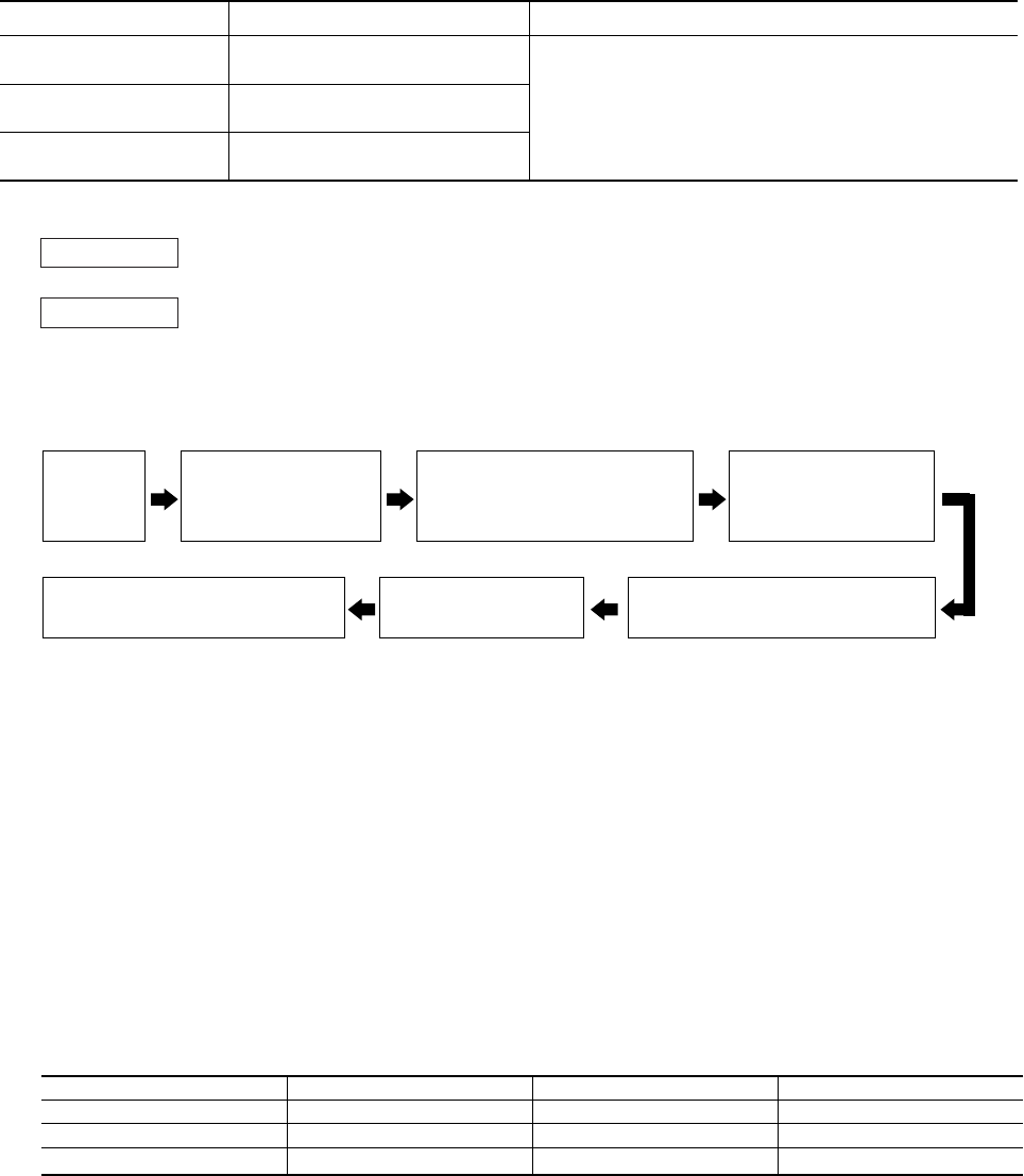
Check of inspection display [In-
door/outdoor unit PCB, remote
controller or Indication board]
Check of inspection display [In-
door/outdoor unit PCB, remote
controller or Indication board]
Power supply check
(indoor/outdoor unit)
Replacement or repair of defective
parts Test run/adjustment
Check of unit
controller
Indoor unit
Outdoor unit
: Press the ON/OFF button on the remote controller. Or disconnect and reconnect the power supply connector
(CNW1 or CNW0) on the indoor unit control PCB or turn the main power supply OFF.
: Turn the main power supply OFF.
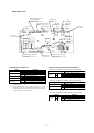
(3) Error diagnosis procedures at the indoor unit side
To diagnose the error, measure the voltage (AC, DC), resistance, etc. at each connector around the circuit board of indoor unit
based on the inspection display or the operation state of unit (no operation of compressor or blower, no switching of 4-way valve,
etc.) If any defective parts are discoverd, replace with the assembly of parts as shown below.
(a) Single-unit replacement parts for circuit board of indoor unit. (Peripheral electric parts for circuit board.)
Indoor unit printed circuit board, thermistor (return, heat exchanger), operating switches, limit switches, transformers, fuses.
Note (1) Use normal inspection methods to determine the condition of strong electrical circuits and frozen cycle parts.
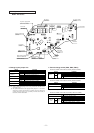
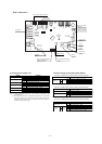
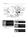
(b) Replacement procedure of indoor unit microcomputer printed circuit board
Microcomputer printed circuit board can be replaced with following procedure.
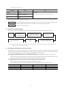
(i) Confirm the parts numbers. (Refer to the following parts layout drawing for the location of parts number.)
PJA505A122ZD
PJA505A122ZC
PJA505A128ZF
Parts number
FDTA 151~401
FDTA 501, 601
FDE
Model
FDKA 151~251
FDKA 301
FDUR
Model
PHA505A018ZF
PHA505A018ZG
PJA505A131ZC
Parts number