


-
22
-
W
CNI
F2
T8
CN
CNQ
CNE
CNI3
CNW
CNI2CNV1
CNM
F3
T1
T5
T4
T2
F1
CNL CNTR
SW6
SW7
T7
T6
VU
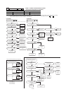
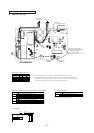
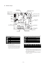
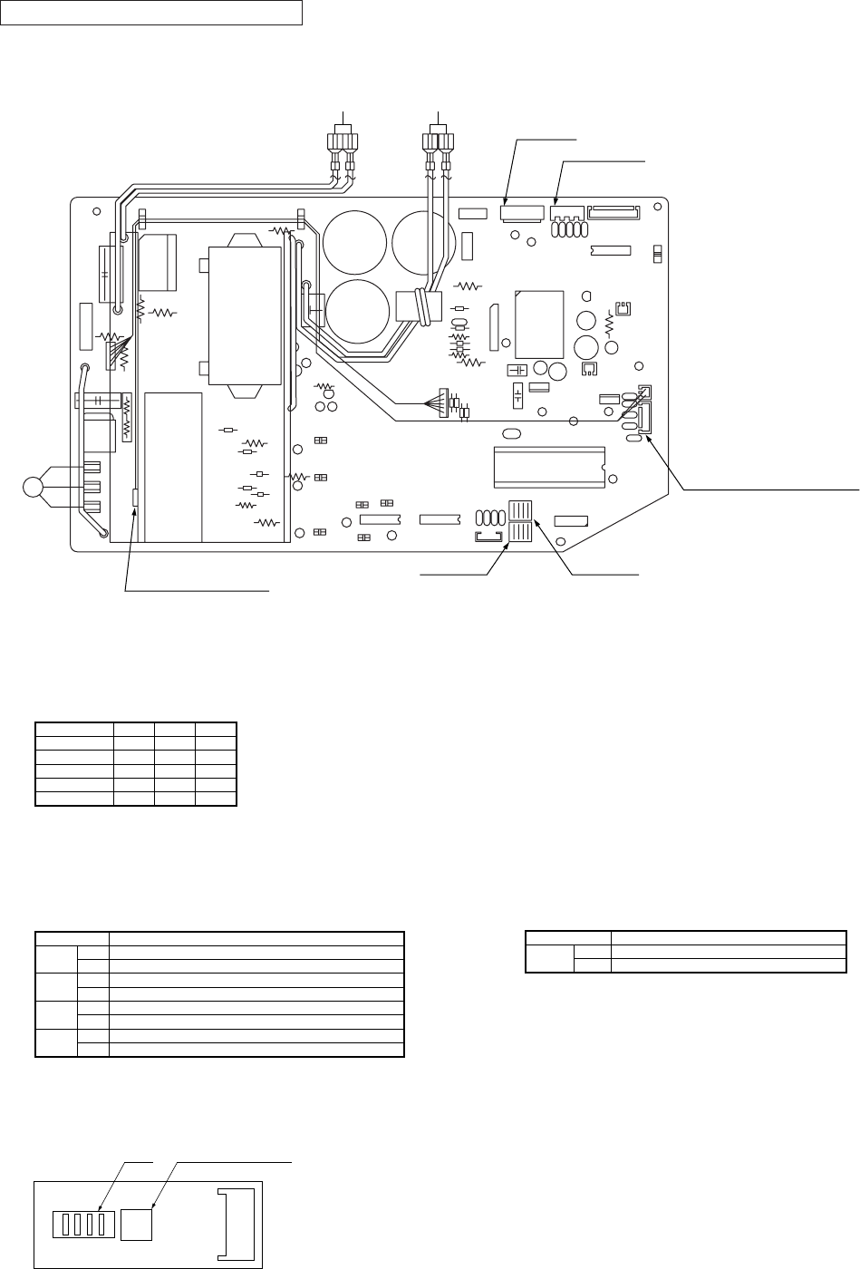
Outdoor air temp. thermistor,
Outdoor heat exchanger themistor,
Discharge pipe thermistor
(Tho-A, Tho-R, Tho-D)
DIP switch
(SW7)
Fan motor
Reactor
Stepping motor
Power transistor thermistor
(Tho-IPM)
DIP switch
(SW6)
Sub PCB
(Noise filter)
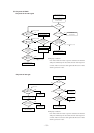
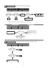
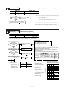
● Function of DIP switches (SW5) (Usually all turned OFF)
Defrost Setting Select For cold regions.
Normal
Low refrigerant protection control-Effective
Low refrigerant protection control-Invalid
Test run operation-Heating
Test run operation-Cooling
SW5-1
SW5-2
SW5-3
SW5-4
ON
OFF
ON
OFF
ON
OFF
ON
OFF
Snow-guard fan control-Effective
Snow-guard fan control-Invalid
Switch Function
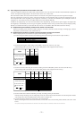
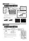
● Change by the jumper wire
SW5
SW5 SW9
Test run operation switch
1234
SW9
CNQ1
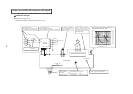
Parts layout on the outdoor unit PCB
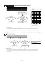
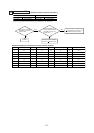
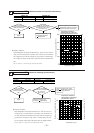
S FDCVA151~251 type
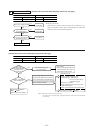
151 201 251
Model
None
None
With
None
With
None
None
None
None
With
None
None
None
With
With
JA1 (SW7-1)
JA5 (SW6-1)
JA6 (SW6-2)
JA7 (SW6-3)
JA8 (SW6-4)
Notes (1) “None” means that jumper wire is not provided on the PCB or the connection is cut
Notes (2) The replacement PCB is not equipped with jumper wires JA1 and JA5~JA8. Instead, SW6 and 7
are mounted in the same position and have the same functions as jumper wires JA1 and JA5~JA8.
Carry out the local settings in accordance with the table using SW6 and 7.
Note (1) “None” means that jumper wire is not provided on the
PCB or the connection is cut.
Model selection-Energy saving
Model selection-Standerd
JA3
(SW7-3)
with
None
Switch Function
● Change by the JA3
External PCB