


-
23
-
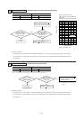
C6
C5
L6
L5
C7
C13
IC12
L7
C6
C8
L8
L10
C9
C10
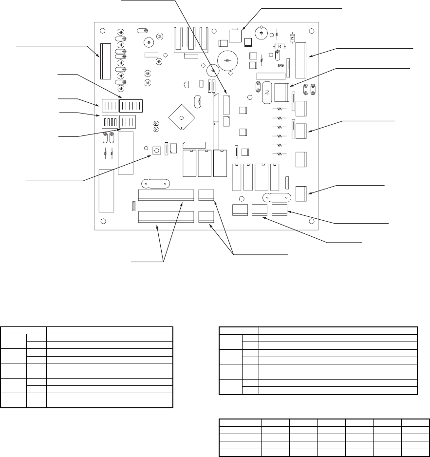
SW6
SW2
KN1
CNM1
CNE
CNA2
X04 X03 X02
X07 X05 X01 X06
CNM2
CNM3
CNS CNO
CNRCNP3CNP1CNP2
CNA1
CNV1
CNW
C3
KN2
CNM4
LED-R
LED-G
SW4
SW5
L11
L12
CNQ
CT2
CT1
J4
J3
J2
J1
J8
J7
J6
J5
1234
C12
C11
C4
C1
C2
HT1
SW3
J14
J13
J12
J11
J15
J16
CNL
SW3
SW6
SW5
SW4
SW2
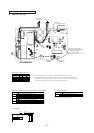
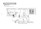
(Test run operation switch)
Fan motor
Capacitor for FMo
Stepping motor
(Tho-A, Tho-D, Tho-R1, 2)
Outdoor unit power supplly
PCB power supply connector
(Primary side)
High pressure switch
(63H1)
Crankcase heater
Magnetic contactor
(52C)
4 way valve
PCB power supply connector
(Secondary side)
Outdoor air thermistor,
Outdoor heat exchanger
thermistor,
Discharge pipe thermistor
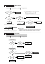
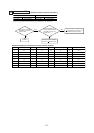
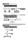
S FDCA301~601 type
1 Phase
3 Phase
Cooling
Heating
Defrost recovery temperature 14ºC
Defrost recovery temperature (See page 88)
Defrost prohibited temperature 45 min.
Defrost prohibited temperature 37 min.
J1
(SW4-1)
with
None
(1)
J2
(SW4-2)
with
None
(1)
J6
(SW6-2)
with
None
(1)
J7
(SW6-3)
J8
(SW6-4)
with
None
(1)
None
(1)
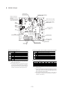
Switch Function
-
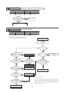
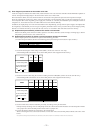
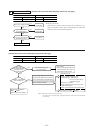
● Change by the jumper wire ● Function of DIP switches (SW5) (Usually all turned OFF)
Defrost Setting Select For cold regions.
Normal
Low refrigerant protection control-Effective
Low refrigerant protection control-Invalid
Test run operation-Heating
Test run operation-Cooling
SW5-1
SW5-2
SW5-3
SW5-4
ON
OFF
ON
OFF
ON
OFF
ON
OFF
Snow-guard fan control-Effective
Snow-guard fan control-Invalid
Switch Function
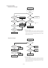
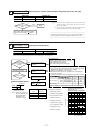
Notes (1) “None” means that jumper wire is not provided on the PCB or the
connection is cut
Notes (2) The replacement board is not equipped with jumper wires J11~J13.
Instead, SW3 is mounted in the same position and has the same func-
tions as jumper wires J11~J13. Carry out the local settings in accor-
dance with the above table using SW3.
(3) The overcurrent setting value becomes the above setting value (A)
automatically in accordance with the settings on J11(SW3-1) ~
J13(SW3-3) and J1(SW4-1).
Notes (1) “None” means that jumper wire is not provided on the
PCB or the connection is cut
Notes (2) The replacement board is not equipped with jumper
wires JA1~JA8. Instead, SW4 and 6 are mounted in
the same position and have the same functions as
jumper wires JA1~JA8. Carry out the local settings in
accordance with the above table using SW4 and 6.
301HEN
17
301HES
10
401HEN
27
401HES
11
501HES
12
601HES
14
Model
Setting Value (A)
With
None
(1)
None
(1)
With
None
(1)
None
(1)
With
None
(1)
With
With
With
With
J11 (SW3-1)
J12 (SW3-2)
J13 (SW3-3)
With
With
None
(1)
With
None
(1)
With
● Overcurrent Setting