


-
24
-
L
N
E
TB
TB
Red
White
Y/NG
LED1
Red
T1 T5
Red
White
Black
Orange
Yellow
UVW
T6 T7 T8
CM
F2 (250V 20A)
CnTR
Control PCB
Power transistor module
CNI3 T2 T4
6
DC280V
F3 (250V 1A)
F5
(
20A
)
4321
CNI2
FM
0
T21
T22
Sub PCB
(Noise filter)
T24
T25
T26
T30
T27T28CNI1
Orange
Gray To indoor unit
Brown
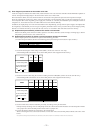
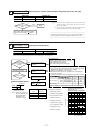
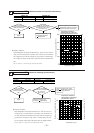
Temperature
[
T
]
(
˚C
)
T
<
80˚C
T
>
80˚C
100
50
0
10
5
0
Thermistor resistance (kΩ)
[
T
<
=
80˚C
]
Thermistor resistance (kΩ)
[
T
>
=
80˚C
]
0 20 50 80 100 120
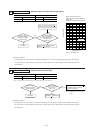
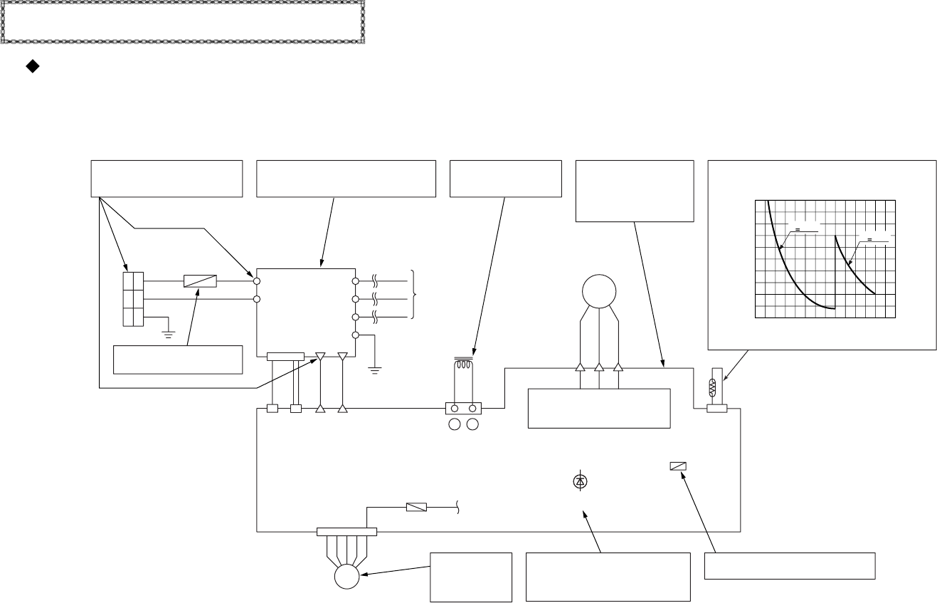
Power transistor thermistor temperature and
resistance characteristics check
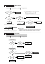
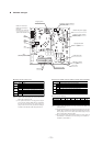
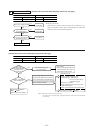
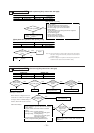
Power transistor module
check: Is there a short cir-
cuit, open circuit or dam-
age? (See 160 page for the
check procedure.)
DC Reactor Continuity
Check: 50 mΩ or higher,
less than 100 mΩ.
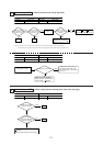
Fuse Check: There should be continuity.
If faulty, replace the control PCB.
When the outdoor
unit fan motor is
abnormal:
(Refer to page 157)
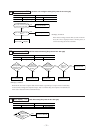
Noise Filter Check:
There should be continuity.
There should be no shorts between phases.
LED1 (Red) Check
Light continuously :
Keeps flashing :
1~3 time flash :
Normal
EEV
Refer to 131 page
Power Supply Check
Measure the power supply at L.N.
(It is normal if it is AC 220/240V.)
❇
Fuse Check: There should be
continuity.
●
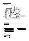
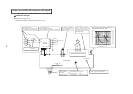
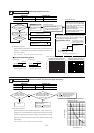
Outdoor unit check points
Check items with the *mark when the power is ON.
Outdoor Unit controller failure diagnosis circuit diagram
FDCVA151~251 type