


12
12
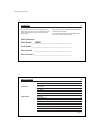
INSTALLATION
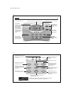
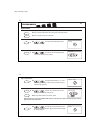
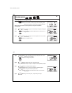
TERMINAL FUNCTION
LABELS (HEAT PUMP) COMMENTS
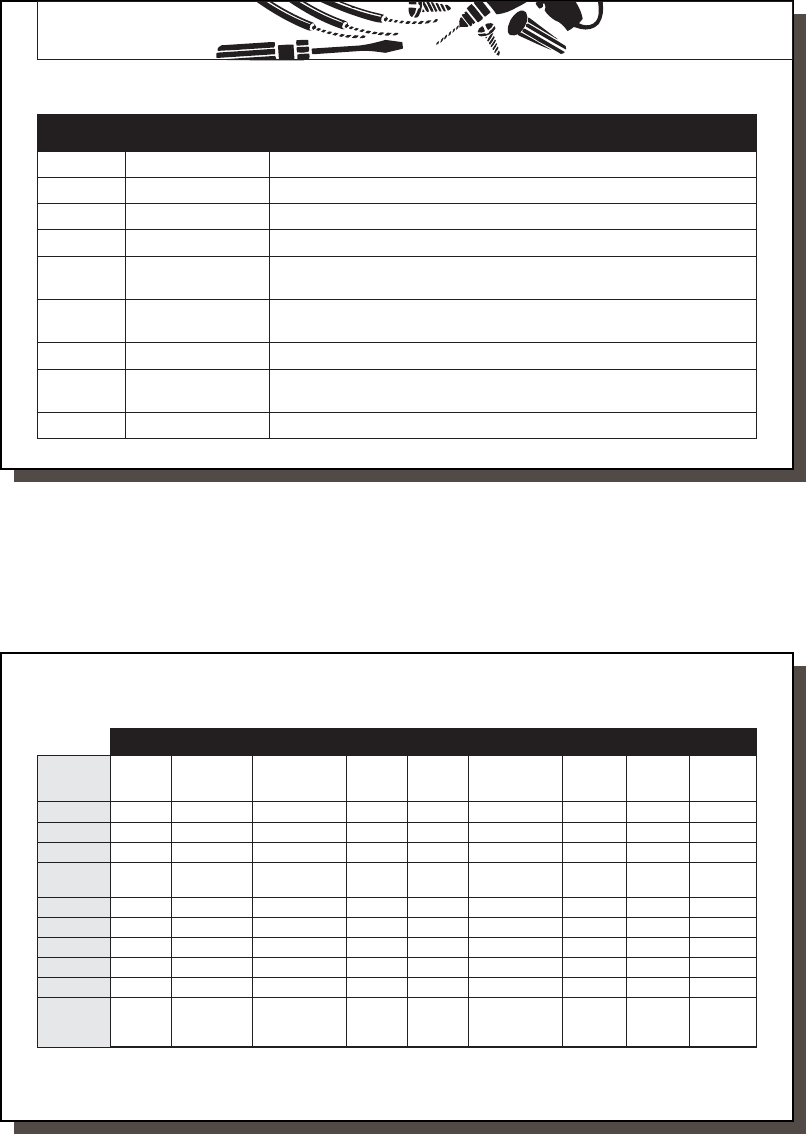
R 24V AC supply Hot wire of 24VAC transformer. Powers the thermostat & system.
Y1 Compressor stage 1 Activates the 1st stage compressor. (Heat or Cool for Heat Pumps)
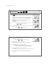
W2 Auxiliary heating Activates the 2nd stage (auxiliary) heating when required.
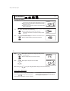
E Emergency heating
Activates Emergency heating ONLY when the System Switch is in Emergency (em) Mode.
O Reversing valve Activates reversing valve in COOL mode. ALWAYS ON in COOL MODE.
(cooling mode)
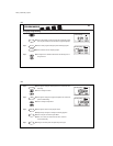
B Reversing valve Activates reversing valve in HEAT mode. ALWAYS ON in HEAT MODE.
(heating mode)
GFan Activates the system Fan. (Can be Auto, On, or Program controlled)
L System monitor Activates System Check LED on the front of thermostat.
(Controlled by the system, not the thermostat.)
C 24V AC common Common wire of 24V AC transformer. REQUIRED for thermostat operation.
TABLE A – TERMINAL DESCRIPTIONS
41652_model44760_web.pmd
13
13
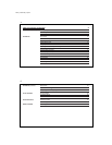
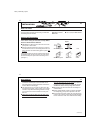
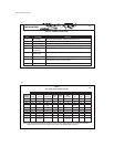
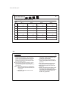
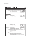
TABLE B
HEAT PUMP CROSS-REFERENCE CHART
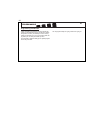
NOTE:
If your heat pump thermostat does not have an E wire, use the provided jumper wire to connect the E terminal to
the W2 terminal, as shown in three examples above. Refer to the Wiring Diagram on page 52.
EXAMPLES OF DIFFERENT SYSTEM TERMINALS
HUNTER BRYANT, RHEEM- TRANE,
TERMINALS CARRIER COLEMAN COMFORTMAKER PAYNE RUUD WEATHERTRON YORK LENNOX (1) LENNOX (2)
R RR R RRRRRV-VR
Y1 Y or Y1 Y Y Y Y Y Y Y M
W2 W2 W2 W1 W2 W2 W W W1 Y
E EEjumper E E X2 jumper E E
to W2 to W2
O OOOOOOR
B BB
G GG G GGGGGF
L L or F L L or X L L X L
C CXC, X, X1 C, C1, X1 X B B C X
Note: W2 wires Note: T wire
no connection no connection