


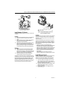
VR8104, VR8204 AND VR8304 INTERMITTENT PILOT COMBINATION GAS CONTROLS
69-1225—48
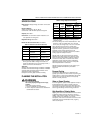
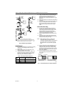
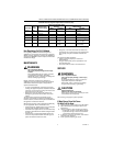
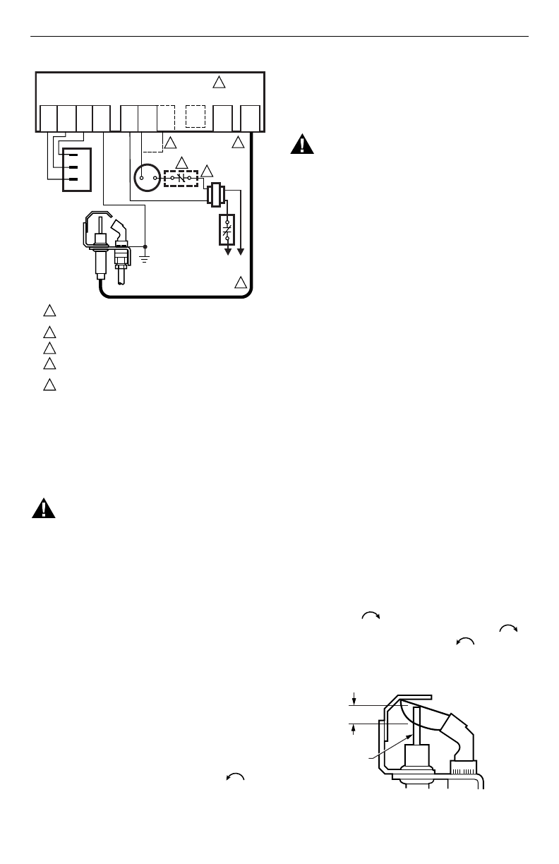
Fig. 8. Typical wiring connections for 24 volt control
in intermittent ignition system with S8600.
STARTUP AND CHECKOUT
WARNING
Fire or Explosion Hazard.
Can cause property damage, severe injury
or death.
1. Do not force the gas control knob on the
appliance. Use only your hand to turn the gas
control knob. Never use any tools.
2. If the knob does not operate by hand, the
control should be replaced by a qualified
service technician.
Gas Control Knob Settings
Gas control knob settings are as follows:
OFF: Prevents pilot and main gas flow through the
control.
ON: Permits gas to flow into the control body. Under
control of the thermostat and intermittent pilot module,
gas can flow to the pilot and main burners.
NOTE: Controls are shipped with the gas control knob
in the ON position.
Turn On System
Rotate the gas control knob counterclockwise to
ON.
Turn On Main Burner
Follow appliance manufacturer instructions or turn up
thermostat to call for heat.
Perform Gas Leak Test
WARNING
Fire or Explosion Hazard.
Can cause property damage, severe injury
or death.
Perform Gas Leak Test every time work is done
on a gas system.
IMPORTANT
Do not spray soap and water solution on the
gas control. Do not use an excessive amount of
soap and water solution to perform the gas leak
test. These can damage the control.
Gas Leak Test
1.
Paint pipe connections upstream of the gas control
with rich soap and water solution. Bubbles indicate
a gas leak.
2.
If a leak is detected, tighten the pipe connections.
3.
Light the main burner. Stand clear of the main
burner while lighting to prevent injury caused from
hidden leaks that could cause flashback in the
appliance vestibule.
4.
With the main burner in operation, paint the pipe
joints (including adapters) and the control inlet and
outlet with rich soap and water solution.
5.
If another leak is detected, tighten the adapter
screws, joints, and pipe connections.
6.
Replace the part if a leak cannot be stopped.
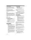
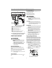
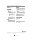
Check and Adjust Pilot Flame
The pilot flame should envelop 3/8 to 1/2 in. (10 to 13
mm) of the tip of the igniter-sensor. See Fig. 9. If the pilot
flame is small or lazy, the inlet gas pressure may be too
low, or the pilot orifice may be partially clogged. Check
and repair as necessary. If the pilot flame is hard and
noisy, the inlet gas pressure may be too high. The gas
control has a pilot adjustment mechanism to reduce the
pilot flow if necessary. If pilot adjustment is necessary,
proceed as follows:
1.
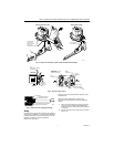
Remove pilot adjustment cover screw. See Fig. 6.
2.
The pilot adjustment is shipped at the full pilot gas
flow rate. Turn the inner adjustment screw
clockwise if the inlet pressure is too high.
Turn the inner adjustment screw clockwise
to decrease or counterclockwise to increase
pilot flame.
3.
Replace the cover screw after the adjustment to
prevent gas leakage.
Fig. 9. Proper flame adjustment.
MV MV/PV PV
GND
(BURNER)
24V
GND
24V
SPARK
S8600
POWER SUPPLY. PROVIDE DISCONNECT MEANS
AND OVERLOAD PROTECTION AS REQUIRED.
ALTERNATE LIMIT CONTROLLER LOCATION.
MAXIMUM WIRE LENGTH 3 ft [.9 m].
CONTROLS IN 24V CIRCUIT MUST NOT BE IN
GROUND LEG TO TRANSFORMER.
FOR MODULE WITH TH-W TERMINAL AND VENT DAMPER
PLUG, CONNECT THERMOSTAT TO TH-W. LEAVE
24V OPEN. DO NOT REMOVE VENT DAMPER PLUG.
1
2
3
4
5
M9056
GROUND
PILOT GAS
SUPPLY
2
4
3
Q345, Q346,
Q348, Q362, Q381
PILOT BURNER/
IGNITER-SENSOR
L1
(HOT)
1
L2
LIMIT
CONTROLLER
THERMOSTAT
5
TH-W
(OPT)
VENT
DAMPER
PLUG
(OPT)
5
GAS CONTROL
TERMINALS
PV
PV/MV
MV
SENSE
PROPER FLAME
ADJUSTMENT
IGNITER-
SENSOR
M3080A
3/8 TO 1/2 INCH
(10 TO 13 mm)