


VR8104, VR8204 AND VR8304 INTERMITTENT PILOT COMBINATION GAS CONTROLS
69-1225—410
4.
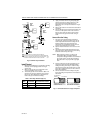
With main burner operating, check the gas control
flow rate using the meter clocking method or check
pressure using a manometer connected to the
outlet pressure tap on the gas control. See Fig. 6.
5.
If necessary, adjust the high pressure regulator to
match the appliance rating. See Tables 8A and 8B
for factory-set nominal outlet pressure and
adjustment range.
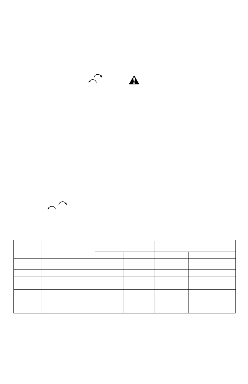
a. Remove the pressure regulator adjustment cap
(Fig. 6).
b. Using a screwdriver, turn the inner adjustment
screw for HI pressure clockwise to
increase or counterclockwise to
decrease the gas pressure to the burner.
6.
After high pressure has been checked, check low
pressure regulation. Two-stage appliance
operating sequences vary. Consult the appliance
manufacturers instructions for the specific
operating sequence and regulator adjustment
procedure for the appliance in which the control is
installed and for instructions on how to prevent the
control from moving to high stage while checking
the low pressure regulator setting.
7.
Check the low rate manifold pressure listed on the
appliance nameplate. Gas control low rate outlet
pressure should match this rating.
8.
With main burner operating, check the gas control
flow rate as before (using the meter clocking
method or check pressure using a manometer
connected to the outlet pressure tap on the
control).
9.
If necessary, adjust the low pressure regulator to
match the appliance rating. See Tables 8A and 8B
for factory-set nominal outlet pressure and
adjustment range.
a. Remove the pressure regulator adjustment cap
(Fig. 6).
Using a screwdriver, turn the inner adjustment screw for
LO pressure clockwise to increase or
counterclockwise to decrease the gas pressure to
the burner.
10.
Once high and low pressure have been checked
and adjusted, replace pressure regulator
adjustment cap. If the desired outlet pressure or
flow rate cannot be achieved by adjusting the gas
control, check the control inlet pressure using a
manometer at the inlet pressure tap of the control.
If the inlet pressure is in the nominal range
(see Tables 8A and 8B), replace the gas control.
Otherwise, take the necessary steps to provide
proper gas pressure to the control.
Check Safety Shutdown Performance
WARNING
Fire or Explosion Hazard.
Can cause property damage, severe injury
or death.
Perform the safety shutdown test any time work
is done on a gas system.
NOTE: Read steps 1 through 7 before starting, and
compare to the safety shutdown or safety
lockout tests recommended for the intermittent
pilot (IP) ignition module. Where different, use
the procedure recommended for the module.
1.
Turn off gas supply.
2.
Set thermostat or controller above room
temperature to call for heat.
3.
Watch for ignition spark or for glow at hot surface
igniter either immediately or following prepurge.
See IP module specifications.
4.
Time the length of the spark operation. See the IP
module specifications.
5.
After the module locks out, open the manual gas
cock and make sure no gas is flowing to the pilot or
main burner. With modules that continue to spark
until the pilot lights or the system shuts down
manually, the pilot should light when the manual
gas control knob is opened.
6.
Set the thermostat below room temperature and
wait one minute.
7.
Operate system through one complete cycle to
make sure all controls operate properly.
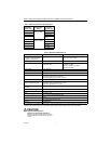
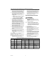
Table 8A. Pressure Regulator Specification Pressures (in. wc).
a
Low Fire setting range for VR8304Q 1/2 in. by 1/2 in. and 1/2 in. by 3.4 in. is 1.5 to 3.0 in. wc.
Model Type
Type of
Gas
Nominal Inlet
Pressure Range
Factory Set Nominal Outlet
Pressure Setting Range
Step Full Rate Step Full Rate
Standard,
Slow
NAT 5.0 to 7.0 — 3.5 — 3.0 to 5.0
LP 12.0 to 14.0 — 10.0 — 8.0 to 12.0
Step NAT 5.0 to 7.0 0.9 3.5 None 0.7 to 1.7
LP 12.0 to 14.0 2.2 10.0 None 1.4 to 5.5
Two-Stage NAT 5.0 to 7.0 — 1.7 Low
3.5 High
—
0.9 to 3.0 Low
a
3.0 to 5.0 High
LP 121.0 to 14.0 — 4.9 Low
10.0 High
— 3.5 to 5.5 Low
8.0 to 11.0 High