


VR8104, VR8204 AND VR8304 INTERMITTENT PILOT COMBINATION GAS CONTROLS
69-1225—46
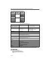
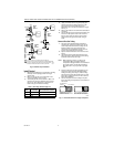
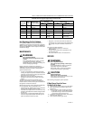
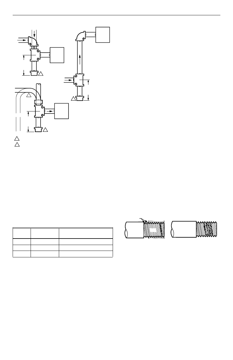
Fig. 3. Sediment trap installation.
Install Control
1.
Mounted 0 to 90 degrees in any direction, including
vertically, from the upright position of the gas
control knob.
2.
Mount so the gas flow is in the direction of the
arrow on the bottom of the control.
3.
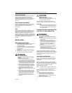
Thread the pipe the amount shown in Table 7 for
insertion into control or adapters. Do not thread
pipe too far. Valve distortion or malfunction can
result if the pipe is inserted too deeply.
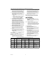
Table 7. NPT Pipe Thread Length (in.).
4.
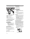
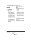
Apply a moderate amount of good quality pipe
compound (do not use Teflon tape) only to the
pipe, leaving two end threads bare. On LP
installations, use a compound resistant to LP gas.
See Fig. 4.
5.
Remove the seals over the control inlet and outlet if
necessary.
6.
Connect the pipe to the control inlet and outlet. Use
a wrench on the square ends of the control. If a
flange is used, place the wrench on the flange
rather than on the gas control. Refer to Fig. 5
and 6.
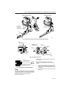
Connect Pilot Gas Tubing
1.
Cut tubing to the desired length and bend as
necessary for routing to the pilot burner. Do not
make sharp bends or deform the tubing. Do not
bend the tubing at the gas control after the
compression nut is tightened, because this can
result in gas leakage at the connection.
2.
Square off and remove burrs from the end of the
tubing.
3.
Unscrew the brass compression fitting from the
pilot outlet (Fig. 6). Slip the fitting over the tubing
and slide out of the way. See Fig. 7.
NOTE: When replacing a control, cut off the old
compression fitting and replace with the
compression fitting provided on the combination
gas control. Never use the old compression
fitting because it may not provide a gas-tight
seal.
4.
Push the tubing into the pilot gas tapping on the
outlet end of the control until it bottoms. While
holding the tubing all the way in, slide the fitting
into place and engage the threads; then turn until
finger tight. Tighten one more turn with a wrench,
but do not overtighten.
5.
Connect the other end of the tubing to the pilot
burner according to the pilot burner manufacturer’s
instructions.
Fig. 4. Use moderate amount of pipe compound.
Pipe
Size
Thread Pipe
this Amount
Maximum Depth Pipe can
be Inserted into Control
3/8 9/16 3/8
1/2 3/4 1/2
3/4 13/16 3/4
GAS
CONTROL
GAS
CONTROL
HORIZONTAL
DROP
PIPED
GAS
SUPPLY
PIPED
GAS
SUPPLY
3 IN.
(76 MM)
MINIMUM
3 IN.
(76 MM)
MINIMUM
RISER
GAS
CONTROL
TUBING
GAS
SUPPLY
HORIZONTAL
DROP
3 IN.
(76 MM)
MINIMUM
RISER
M3077
2
1
2
2
1
2
ALL BENDS IN METALLIC TUBING SHOULD BE SMOOTH.
CAUTION: SHUT OFF THE MAIN GAS SUPPLY BEFORE REMOVING
END CAP TO PREVENT GAS FROM FILLING THE WORK AREA. TEST
FOR GAS LEAKAGE WHEN INSTALLATION IS COMPLETE.
TWO IMPERFECT
THREADS
GAS CONTROL
THREAD PIPE THE AMOUNT
SHOWN IN TABLE FOR
INSERTION INTO GAS CONTROL
APPLY A MODERATE AMOUNT OF
PIPE COMPOUND TO PIPE ONLY
(LEAVE TWO END THREADS BARE).
M3075B
PIPE