


VR8104, VR8204 AND VR8304 INTERMITTENT PILOT COMBINATION GAS CONTROLS
7 69-1225—4
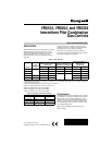
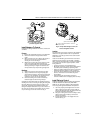
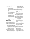
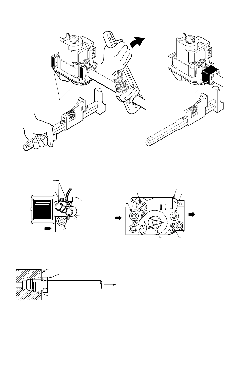
Fig. 5. Proper use of wrench on gas control with and without flanges.
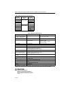
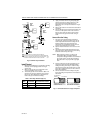
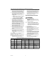
Fig. 6. Top view of gas control.
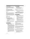
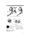
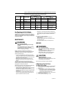
Fig. 7. Always use new compression fitting.
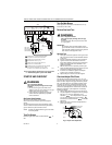
Wiring
Follow the wiring instructions furnished by the appliance
manufacturer, if available, or use the general instructions
provided below. When these instructions differ from the
appliance manufacturer, follow the appliance
manufacturer instructions.
All wiring must comply with applicable electrical codes
and ordinances.
Disconnect power supply before making wiring
connections to prevent electrical shock or equipment
damage.
1.
Check the power supply rating on the gas control
and make sure it matches the available supply.
Install a transformer, thermostat and other controls
as required.
2.
Connect control circuit to the gas control terminals.
See Fig. 8.
APPLY WRENCH
FROM TOP OR
BOTTOM OF GAS
CONTROL TO
EITHER SHADED AREA
WHEN FLANGE IS NOT USED
APPLY WRENCH
TO FLANGE ONLY
WHEN FLANGE IS USED
M3079
HI-LO
ADJUSTMENT SCREWS
(UNDER CAP)
REGULATOR
VENT COVER
INLET
INLET
OUTLET
M10968A
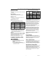
HI
LO
OUTLET
PRESSURE
TAP
WIRING
TERMINALS (3)
INLET
PRESSURE TAP
PRESSURE REGULATOR
ADJUSTMENT
(UNDER CAP SCREW)
PILOT OUTLET
PILOT ADJUSTMENT
(UNDER CAP SCREW)
GAS
CONTROL
KNOB
TWO-STAGE
PRESSURE
REGULATOR
MODEL
GAS CONTROL
TIGHTEN NUT ONE TURN
BEYOND FINGER TIGHT.
FITTING BREAKS OFF AND CLINCHES
TUBING AS NUT IS TIGHTENED.
TO PILOT
BURNER
M3076A