


VR8104, VR8204 AND VR8304 INTERMITTENT PILOT COMBINATION GAS CONTROLS
5 69-1225—4
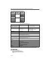
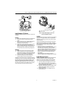
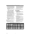
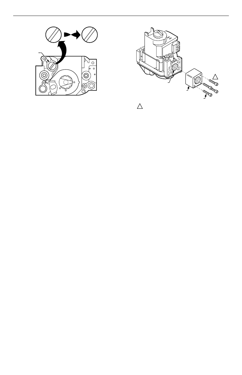
Fig. 1. Top view of convertible
pressure regulator cap.
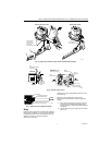
Install Adapters To Control
If adapters are being installed on the control, mount them
as follows:
Flanges
1.
Choose the appropriate flange for your application.
2.
Remove the seal over the gas control inlet or
outlet.
3.
Make sure that the O-ring is fitted in the groove of
the flange. If the O-ring is not attached or is
missing, do not use the flange.
4.
With the O-ring facing the control, align the screw
holes on the gas control with the holes in the
flange. Insert and tighten the screws provided with
the flange. See Fig. 2. Tighten the screws to 25
inch-pounds of torque to provide a gas-tight seal.
Bushings
1.
Remove the seal over the control inlet or outlet.
2.
Apply a moderate amount of good quality pipe
compound to the bushing, leaving two end threads
bare. On an LP installation, use compound that is
resistant to LP gas. Do not use Teflon tape.
3.
Insert the bushing in the control and carefully
thread the pipe into the bushing until tight.
Complete the instructions below for installing the piping,
installing the control, connecting the pilot gas tubing and
the wiring. Make sure the leak test you perform on the
control after completing the installation includes leak
testing the adapters and screws. If you use a wrench on
the valve after the flanges are installed, use the wrench
only on the flange, not on the control. See Fig. 5.
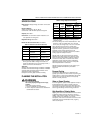
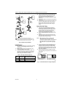
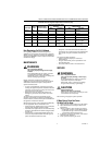
Fig. 2. Firmly fasten flange to valve, but
do not overtighten screws.
Location
The combination gas control is mounted in the appliance
vestibule on the gas manifold. If this is a replacement
application, mount the gas control in the same location
as the old control.
Locate the combination gas control where it cannot be
affected by steam cleaning, high humidity, or dripping
water, corrosive chemicals, dust or grease accumulation
or excessive heat. To assure proper operation, follow
these guidelines:
• Locate gas control in a well-ventilated area.
• Mount gas control high enough above cabinet bottom
to avoid exposure to flooding or splashing water.
• Assure the ambient temperature does not exceed the
ambient temperature ratings for each component.
• Cover gas control if appliance is cleaned with water,
steam, or chemicals or to avoid dust and grease
accumulation.
• Avoid locating gas control where exposure to
corrosive chemical fumes or dripping water are likely.
Install Piping to Control
All piping must comply with local codes and ordinances
or with the National Fuel Gas Code (ANSI Z223.1,
NFPA No. 54), whichever applies. Tubing installation
must comply with approved standards and practices.
1.
Use new, properly reamed pipe that is free from
chips. If tubing is used, make sure the ends are
square, deburred and clean. All tubing bends must
be smooth and without deformation.
2.
Run pipe or tubing to the control. If tubing is used,
obtain a tube-to-pipe coupling to connect the
tubing to the control.
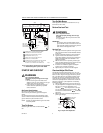
3.
Install a sediment trap in the supply line to the
control. See Fig. 3.
PRESSURE
REGULATOR
CAP
M11678
N
A
T
N
A
T
L
P
L
P
N
A
T
N
A
T
OR
OTHER SIDE
OF CAP
M9046
VALVE OUTLET
FLANGE
9/64 INCH HEX SCREWS (4)
DO NOT OVERTIGHTEN SCREWS. TIGHTEN TO
25 INCH-POUNDS.
1
1