


BACNET INTEGRATION MANUAL FOR TB7200 & TB7300 SERIES THERMOSTATS
5 63-4524—01
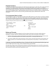
NETWORK CONFIGURATION
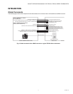
EIA-485 networks use a daisy chain configuration. A daisy chain means that there is only one main cable and every network
device is connected directly along its path.
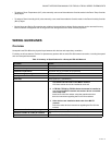
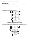
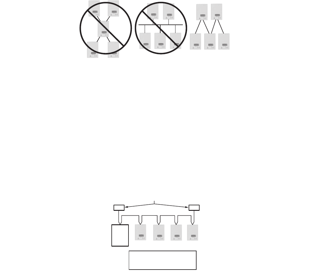
Figure 1 illustrates two improper network configurations and the proper daisy chain configuration.
Other methods of wiring an EIA-485 network may give unreliable and unpredictable results. There are no troubleshooting
methods for these types of networks. Therefore, a great deal of site experimentation may have to be done, making this a difficult
task with no guarantee of success. Honeywell will only support daisy chain configurations.
Fig. 1. Three different network configurations: star, bus, and daisy chain.
Only the daisy chain configuration is correct for an EIA-485 network.
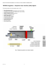
Maximum Number of Devices
A maximum of 64 nodes is allowed on a single daisy chain segment. A node is defined as any device (controller, thermostat,
repeater, etc.) connected to the RS485 network. Terminators do not count as a node.
NOTE: Biasing is not required with this series of devices.
To determine the number of nodes on a network, add the following:
• One node for each device, including the controller
• One node for each repeater on the chain
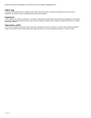
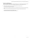
For the example in Figure 2, we have one node for the controller, plus 4 for the thermostats for a total of 5 nodes.
Fig. 2. Five nodes network example.
If you have more than 64 devices, then repeaters are required to extend the network.
M32571
DAISY CHAIN
CONFIGURATION
BUS CONFIGURATION
STAR CONFIGURATION
EOL
NODE 2
NODE 3
NODE 4
NODE 5
SC
EOL
NODE 1
END OF LINE RESISTOR DOES
NOT COUNT AS A NODE
M32572
LEGEND
EOL: END OF LINE RESISTOR
SC: SUPERVISORY CONTROLLER