


T7100D,E,F MICROELECTRONIC COMMERCIAL THERMOSTATS AND Q7100A,C,D SUBBASES
68-0163—3
7
Always check the display to determine if the thermostat is
controlling to the comfort, temporary or remote setpoint.
Temporary is displayed when the Override key is pressed or
the occupancy sensor or remote setback timer is
energized.
CAUTION
Equipment Damage.
Driving multiple T7100 overrides from a single
source will cause electrical damage.
The override terminals on the T7100 must be
activitated from a dedicated source.
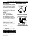
If you need to drive several T7100 Thermostats from a single
source, use an isolation relay at each T710 and connect the
isolation relay contacts to the D terminals of each T7100.
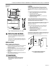
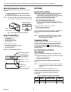
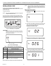
Setting Keypad Lockout Switch
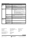
The DIP switch on the back of the thermostat activateds the
Installer Setup lockout feature. DIP switch 1 must be set to the
ON position (up) to activate the lockout feature. See Fig. 12.
The factory setting is off (down). Remove the thermostat from
the wallplate and set the switch to ON if keypad lockout is
desired. The level of lockout is determined by the Installer
Setup number 40.
—To advance to the next Installer Setup, press the
Information i key.
—To change a setting, use the increase ▲ and decrease
▼ keys.
—To exit the Installer Setup, press and hold the Information
i key until the display returns to normal (approximately
three seconds). The display scrolls the numbers
backward to get to the normal display. The Installer Setup
is automatically exited if no key presses are made for five
minutes.
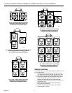
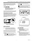
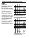
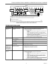
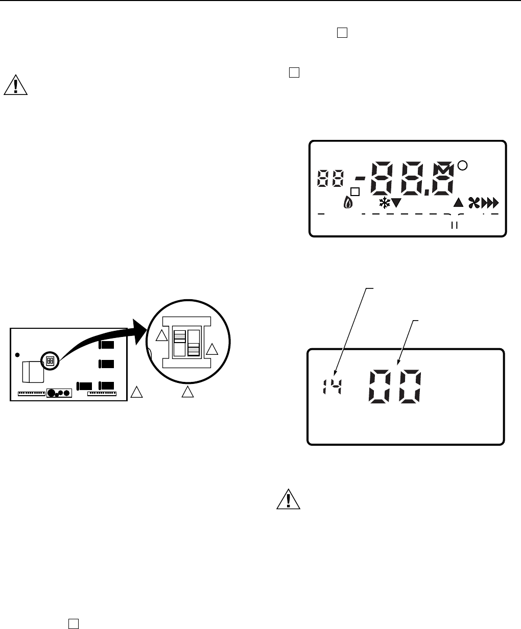
Fig. 13. LCD display of all segments.
Fig. 12. Set Installer Setup lockout
DIP switch 1 on back of thermostat.
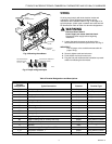
INSTALLER SETUP
NOTE: For most applications, the thermostat factory
settings do not need to be changed. Review the
factory settings in Table 6 and if no changes are
necessary, go to the Installer System Test section.
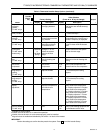
The Installer Setup is used to customize the thermostat to
specific systems. Installer Setup numbers are listed in Table 6.
The table includes all the configuration options available.
A combination of key presses is required to use the Installer
Setup features.
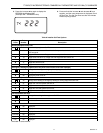
—To enter the Installer Setup, press and hold the
Information i key with the increase ▲ and decrease ▼
keys until the first number is displayed. All display
segments appear for approximately three seconds before
the number is displayed. See Fig. 13 and 14.
ON
1
2
M10235
BACK OF THERMOSTAT
1
2
1
2
DIP 1 IS ON
DIP 2 IS NOT USED.
Em HeatOffCool Auto Only
Heat Cool
OnAuto
System Fan
Room
Outdoor
Em Ht Temporary Setting
Wait
%Humid
Aux Ht
Remote
Repl
Batt
M4844
M10407
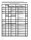
INSTALLER SETUP
NUMBER DISPLAY
(COLUMN 2 OF TABLE 6)
FACTORY SETTING OR
OTHER CHOICE DISPLAY
(COLUMN 3 OR 5 OF TABLE 6)
Fig. 14. Installer Setup and setting display.
CAUTION
Equipment Damage.
Equipment can be damaged by the system
running without the fan.
Heat pump and electric heat systems must be
configured to 01 in Installer Setup 02.
IMPORTANT
Only configurable numbers are shown on the device.
Example: If the thermostat does not have the
changeover feature, Installer Setup 12 is not
displayed. Review Table 6 factory settings and mark
desired changes in the Actual Setting column. When
the Installer Setup is complete, review the settings to
confirm that they match the system.