


T7100D,E,F MICROELECTRONIC COMMERCIAL THERMOSTATS AND Q7100A,C,D SUBBASES
68-0163—3 4
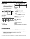
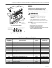
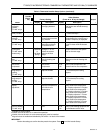
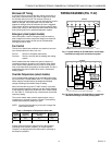
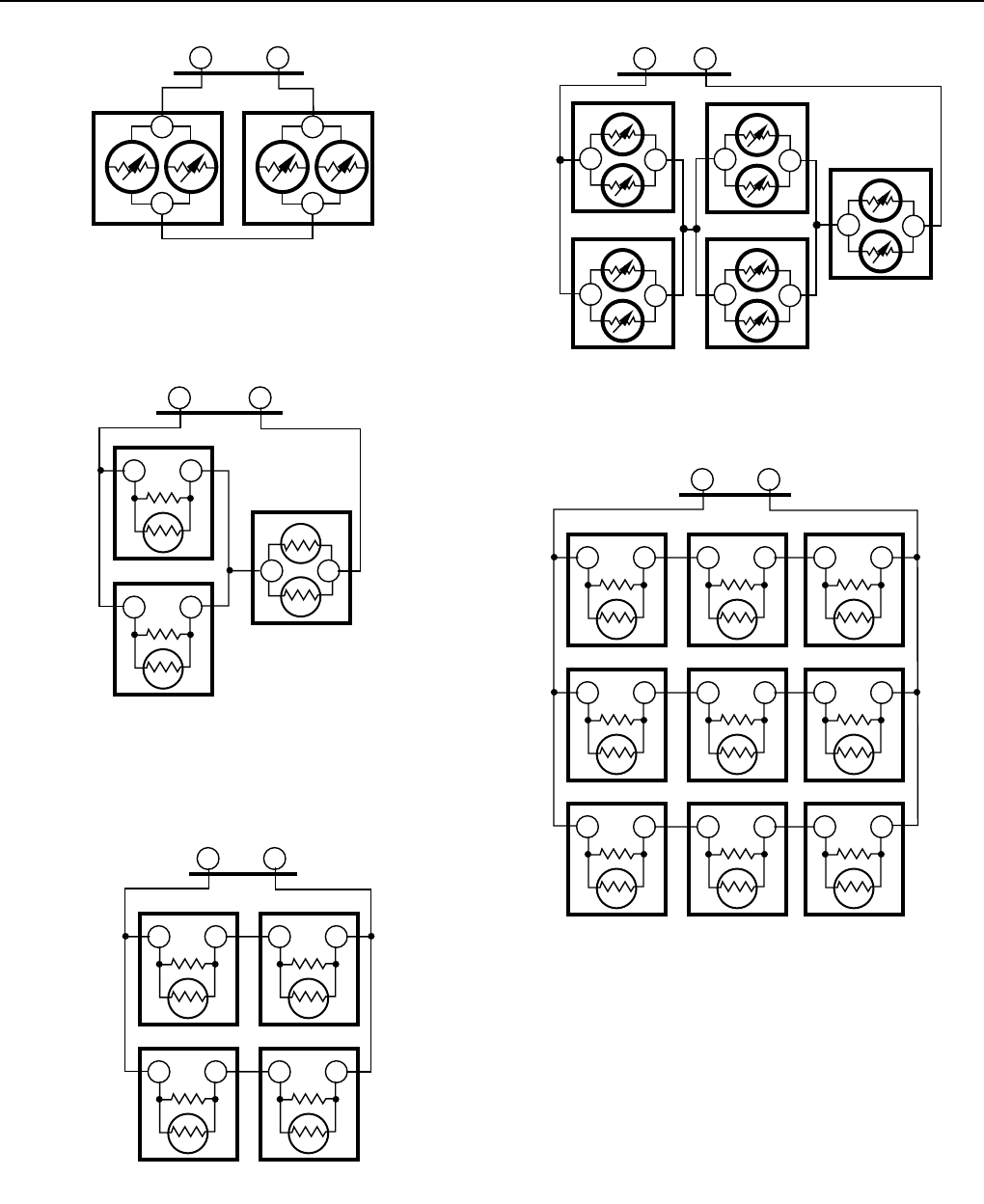
Fig. 3. Two T7047G Sensors providing
temperature averaging network for
T7100/Q7100 Thermostat/Subbase.
M4838
TT
SUBBASE
T
T
T7047GT7047G
T
T
M4839
TT
SUBBASE
TT
T7047C
TT
T7047C
TT
T7047G
M4840
TT
TT
SUBBASE
T7047C
TT
T7047C
TT
T7047C
TT
T7047C
M4841
TT
SUBBASE
T
T
T7047G
T
T
T7047G
T
T
T7047G
T
T
T7047G
T
T
T7047G
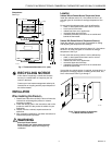
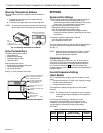
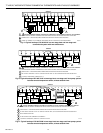
Fig. 4. Two T7047C Sensors and one T7047G Sensor
providing temperature averaging network
for T7100/Q7100 Thermostat/Subbase.
Fig. 5. Four T7047C Sensors providing
temperature averaging network for
T7100/Q7100 Thermostat/Subbase.
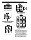
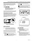
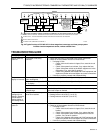
Fig. 6. Five T7047G Sensors providing
temperature averaging network for
T7100/Q7100 Thermostat/Subbase.
Fig. 7. Nine T7047C Sensors providing
temperature averaging network for
T7100/Q7100 Thermostat/Subbase.
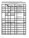
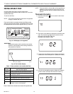
Subbase Installation
The subbase can be mounted horizontally on the wall or on a 2
in. x 4 in. wiring box.
1. Position and level the subbase (for appearance only).
The thermostat functions properly even when not level.
2. Use a pencil to mark the mounting holes. See Fig. 8.
3. Remove the subbase from the wall and drill two 3/16 inch
holes in the wall (if drywall) as marked. For firmer
material such as plaster, drill two 7/32 inch holes.
4. Gently tap anchors (provided) into the drilled holes until
flush with the wall.
5. Position the subbase over the holes, pulling wires
through the wiring opening.
6. Loosely insert the mounting screws into the holes.
7. Tighten mounting screws.
M4842
TT
TT
SUBBASE
T7047C
TT
T7047C
TT
T7047C
TT
T7047C
TT
T7047C
TT
T7047C
TT
T7047C
TT
T7047C
TT
T7047C