


MS-9600LS Series Manual — P/N 52646:B2 2/12/2010 99
Master Programming Level Programming
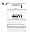
Zones Available
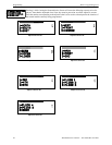
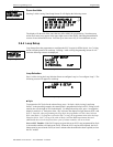
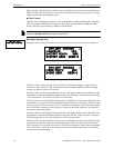
Pressing 2 while viewing Zone Setup Screen #3 will display the following screen:
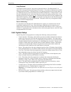
The display will show all of the zones that are still available for programming. Note that an up
and/or down arrow may appear in the upper right corner of the display, indicating that additional
screens of zone information exists. Press the up or down arrow key to view additional screens.
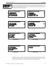
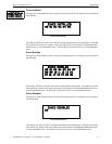
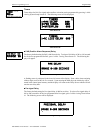
3.6.4 Loop Setup
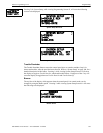
Loop Setup allows the programmer to configure the SLC Loop(s) for NFPA Style 4, 6 or 7 wiring
and to select the protocol for each loop. Pressing 1 while viewing Programming Screen #2 will
cause the following screen to be displayed:
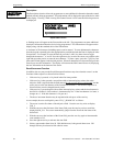
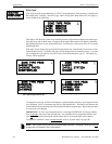
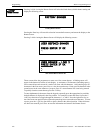
Loop Selection
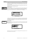
Press 1 while viewing the Loop Selection Screen to configure Loop1 or 2 to configure Loop 2. The
following screens will appear for each loop.
Style
To program the SLC Style for the selected loop, press 1 for Style, while viewing Loop Setup
Screen. In the preceding example, the control panel is programmed for Style 4 SLC wiring as indi-
cated by the 4 to the right of Style in the display. To change the wiring style, press 1 to toggle the
display to read Style 6. Each press of the 1 key will cause the display to toggle between Style 4 and
Style 6. Note that, when programming the Loop Style, the programmer can only select between
Style 4 and Style 6. To program a system for Style 7 wiring, the programmer must select the Loop
Setup for Style 6. Style 7 wiring is the same as Style 6 with the added requirement that each
addressable device on the loop must have a pair of isolator modules, one on each side.
Note on SLC Troubles: If the FACP reports an open fault on an SLC Loop programmed for Style
6, the trouble condition will latch at the FACP. When the SLC Loop has been repaired, the Reset
button must be pressed at the FACP (at least 2 minutes after the trouble has been repaired) to clear
the SLC trouble.
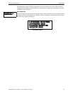
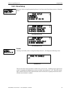
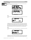
ZONE SETUP
1=ZONE TYPES
2=ZONES AVAILABLE
3=ZONE MESSAGE
Zone Setup Screen #3
ZONES AVAILABLE
01 02 03 04 05 06 07
08 09 10 11 12 13 14
15 16 17 18 19
PROGRAMMING
1=LOOP SETUP
2=SYSTEM SETUP
3=VERIFY LOOPS
Programming Screen #2
LOOP SETUP
1=LOOP 1
2=LOOP 2
3-PROTOCOL CLIP
Loop Selection Screen
LOOP # SETUP
1=STYLE 4
Loop Setup Screen