


188 MS-9600LS Series Manual — P/N 52646:B2 2/12/2010
NFPA Standard-Specific Requirements
NFPA Signaling Systems for Central Station Service (Protected Premises
Unit)/Remote Station
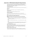
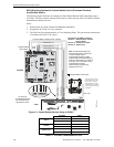
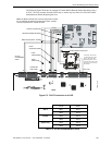
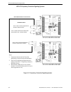
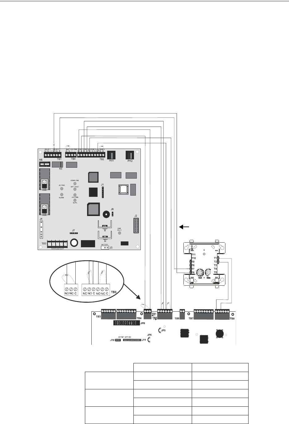
The following figure illustrates an example of Central Station/Remote Station Reporting using a
411UDAC. The relay contacts from the FACP may be used to trip any dialer UL listed for Central
Station/Remote Station Services.
Notes:
1. Reference the 411UDAC Manual for additional information
2. Program the 411UDAC for slave operation
3. The FACP must be programmed for AC Loss Reporting Delay This prevents the transmission
of a trouble on the loss of AC power
TB1
Figure C.1 Central Station Service Using 411UDAC
2.2K
ELR
AC wiring for
411UDAC/FACP must
be connected to the
same branch circuit.
FACP
411UDAC
Alarm Relay
Trouble Relay
Supv. Relay
Monitor Module
ELR resistor
SLC Loop
Monitor Module*
Monitor Module Circuit Input
411UDAC Relay 2 Output (DACT Trouble)
Channel 1/Zone 1
Channel 3/Zone 3
Channel 2/Zone 2
2.2K EOLR
UL listed 2.2K ELRs (P/N 27070)
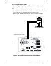
Program the 411UDAC as follows:
Channel 1 - Normally Open Contact
Device (alarm)
Channel 2 - Host Panel Trouble
Channel 3 - Supervisory
Note: The Monitor Module input,
which is being used to monitor the
411UDAC Relay Output
programmed for DACT Trouble
(requires optional 411RK Relay Kit),
must be programmed as ‘Trouble’ at
the FACP. The 411UDAC must be
programmed as a Slave
Communicator (programming
address 64 set to 2).
123
1 2 3 4 5 6 7 8 9 10
123456
9600411a.wmf
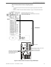
*If the SLC device does
not match the one in this
figure, refer to the SLC
manual appendix, which
contains wiring conversion
charts for type V and type
H modules.
411UDAC FACP
Alarm
TB2-1 TB1-3
TB2-2 TB1-1
Trouble
TB2-3 TB5-3
TB2-4 TB5-2
Supervisory
TB2-5 TB5-6
TB2-8 TB5-4
Table C.1 411UDAC Connections to FACP