


10 MS-9600LS Series Manual — P/N 52646:B2 2/12/2010
+
B
A
T
T
E
R
Y
-
LCD DISPLAY
K
E
Y
P
A
D
I
/
F
O
P
T
D
A
C
T
J
3
J
2
T
B2
T
B
3
J
P
3
J
P
2
S
W
1
JP5
JP6
J
1
7
J16
J
6
J8
J
7
J
1
0
J1
1
R
E
M
O
V
E
T
O
D
I
S
A
B
L
E
L
O
C
A
L
C
H
A
R
G
E
R
D
I
S
A
B
L
E
G
N
D
F
L
T
S
L
C
O
P
T
4
X
T
M
F
O
P
T
B
D
TB4
T
B
4
J
P
8
T
B
5
T
B
6
T
B
7
D
B
9
F
T
B
8
2
1
4
3
6
5
+
+
+
B
+
B
+
B
+
B
+
B
-
B
-
B
-
B
-
1
1
A
+
A
+
A
-
A
-
s
h
i
e
l
d
-
-
-
-
NO NC C
NC NO C N
O NC C
5 4 3 2 1
9 8 7 6
T
X
R
C
V
D
T
R
5 4 3
2 1
25 24 23 22 21 20 19 18 17 16
15 14
9 8 7 613 12 11 10
+
-
I
N
+
O
U
T
+
I
N
-
O
U
T
-
B
+
B
-
BA
+
A
-
A
NC NO C
+
+
+
+
+
+
+
+
+
+
+
+
+
+
+
+
+
+
T
X
R
C
V
D
T
R
G
N
D
G
N
D
B
+
B
-
B
+
B
-
3
3
2
2
4
4
TB1
J
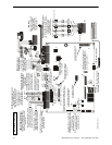
1
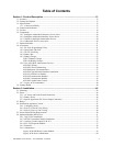
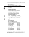
9600udleslayout.wmf
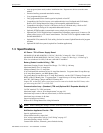
PS2 Keyboard Interface
Flash Memory Load Enable Switch
UP is normal position for switch
DOWN position allows loading of
factory software upgrades
Connector for Optional 2nd
Signaling Line Circuit
Connector for Optional
Onboard DACT-UD
Battery
24 VDC, 26 Amp Hour maximum
(supervised, nonpower-limited)
Auxiliary
Trouble Inputs
#1 2
To disable ground fault detection,
remove jumper/shunt from JP2.
Remove JP3 jumper to disable the FACP
battery charger when using external charger.
JP8- Install NACKEY board in proper
orientation to configure NACs 4
StyleY or 2 Style Z circuits
Connectors for 4XTMF Option Module
Cut this jumper to enable
Supervisory relay when
4XMTF is installed.
Cut this jumper to supervise
the 4XMTF when installed
(see J10 & J11)
(*Factory default relay programming
as shown on circuit board)
circuit number
ELRs 4.7K, 1/2W
NAC #1 NAC #2 NAC #3 NAC #4
Notification Applicance Circuits
Power-limited, supervised circuits
NAC #1, #2, #3, & #4, Style Y (Class B)
3.0 amps max per circuit
JP8 configured for Class B
using NACKEY card
(factory default configuration)
SLC Loop
(Supervised Power-limited)
Refer to the SLC Wring
Manual for detailed
information on wiring
addressable devices for
Style 4, 6, and 7
TERM
(EIA-485)
to LCD-80F
EIA-232 to printer or
personal computer
Power-limited
for EDP-listed equipment
or personal computer with
FACP Upload/Downlad
Utility. 50 foot maximum
within same room.
OR
2 Programmable Relays &
1 Fixed Trouble Relay
(nonsupervised)
Contact Ratings:
2.0 amps @ 30VDC (resistive)
0.5 amp @ 30 VAC (resistive)
Contacts show in normal condi-
tion (AC power with no alarm,
trouble, or supervisory activity).
A fail-safe trouble relay switches
to the NO position during
trouble conditions and
under loss all power.
ACN/ANN-BUS
(EIA-485)
to annunciators
(power-limited,
supervised)
Red
White
Green
Black
Alarm*
NO NC C
Trouble Supervisory*
NO NC C NO NC C
Notification Appliance Circuits
Special Application Power
Power-limited, supervised circuits
NAC #1 & #2 Sytle Z (Class A)
3.0 amps max per circuit
JP8 configured for Class A
using NACKEY card
(See Style Y illustrated
near right edge of board)
NAC #1 NAC #2
Special Application Power
DC Power Outputs (24 VDC)
Power-limited, nonsupervised circuits
Supervise with a power supervision
relay EOLR-1
Nonresettable Power #2 - 24 VDC
filtered, power-limited, (1.5 amps
maximum) Supervision required.
Suitable for powering annunciators.
Nonresettable Power #1 - 24 VDC
filtered, power-limited, (1.5 amps
maximum) Supervision required.
Suitable for powering annunciators.
Resettable Power - 24 VDC filtered,
power-limited, (1.5 amps maximum)
to smoke detectors.
Supervision required.
Important: Removing Ground
Fault Disable jumper JP2 voids
UL/NFPA Style/Class
identification for circuits.
Remove jumper JP2 only with
AHJ (Authority Having
Jurisdiction) approval
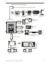
Basic System Connections