


MS-9600LS Series Manual — P/N 52646:B2 2/12/2010 17
Controls and Indicators Product Description
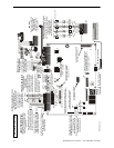
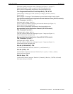
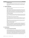
1.3.1 Current Availability
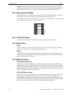
The following figure illustrates the maximum current that is possible for each panel circuit and the
total current available from the FACP power supply.
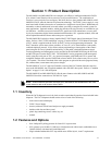
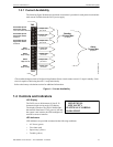
1.4 Controls and Indicators
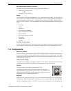
LCD Display
The FACP uses an 80-character (4 lines X 20
characters) high viewing angle LCD display.
The display includes a long life LED backlight
that remains illuminated. If AC power is lost and
the system is not in alarm, the LED backlight will
turn off to conserve batteries.
LED Indicators
LED indicators are provided to annunciate the following conditions:
• AC Power (green)
• Fire Alarm (red)
• Supervisory (yellow)
• Trouble (yellow)
1
2
3
4
5
6
7
8
1
2
3
4
5
6
TB4
TB3
Figure 1.1 Current Availability
powerdist9600ls2.wmf
*The combined output current of all Special Applications Power circuits cannot exceed 1.5 amps in standby. Each
circuit is capable of delivering the full 1.5 amps individually.
Refer to the battery calculations section for additional information.
1.5 amps max
per circuit
1.5 amps max
per circuit
1.5 amps max
per circuit
3 amps max
per circuit
3 amps max
per circuit
3 amps max
per circuit
3 amps max
per circuit
Standby
1.5 Amps Max*
per panel
Resettable Special
Application Power
for 4-wire smoke detectors
Alarm
7 Amps Max
per panel
Resettable Special
Application Power
Power #1
Resettable Special
Application Power
Power #2
NAC 1
Style Y or Z
NAC 2
Style Y or Z
NAC 3
Style Y only
NAC 4
Style Y only
HONEYWELL
LIFE SAFETY
SYSTEM ALL NORMAL
10:00A 020102