


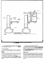

AUXILIARY SWITCH
CONNECTIONS
supplies to de-energize the
The
M9484E
has 1 internal auxiliary switch. The switch
wires are color-coded as follows: solid yellow-normally
closed (N.C.); solid red-common (COM.); solid
blue-normally open (N.O.).
The
M9484F
has 2 internal auxiliary switches which
may be used to prove low fire and high fire positions.
1.
To prove low fire use red (common) and yellow wires
connected to outer (left) switch. This switch makes red to
yellow and breaks red to blue as motor closes.
2.
Wires connected to the inner (right) switch are black
with colored tracers. To prove high fire, use red tracer
(common) and blue tracer wires. The right switch makes
red tracer to blue tracer and breaks red tracer to yellow
tracer as motor opens.
Color coding and switching action are tabulated below
to aid the installer.
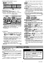
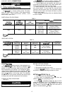
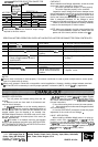
SWITCH/CAM COLOR-CODING:
TABLE 1
CAM
SWITCH
ASSEMBLY
LOCATlON’
LOCATIONa
Left
Outer
Right
Inner
aViewed
from power end of motor.
bSee
Fig. 6.
CAM
COLOR CODE
Red
Blue
SWITCH
WIRESb
COLOR
DESIGNATION
Solid Yellow
Normally Closed (N.C.)
Solid Red
Common (COM.)
Solid Blue
Normally Open (N.O.)
Yellow Tracer
Normally Closed (N.C.)
Red Tracer
Common (COM.)
Blue Tracer
Normally Open (N.O.)
SWITCHING ACTION:
SWITCH
NORMAL
LOCATIONa
FUNCTION
Left
Proves
Low Fire
Position
Right
Proves
High Fire
Position
aViewed
from power end of motor.
bSee
Fig. 9
TABLE 2
CAM
MOTOR
MAKES
BREAKES
POSITIONb
POSITION
Red
Red
High portion of cam
Closing
to to
not in Contact
Yellow
Blue
with Cam follower.
Red Tracer Red Tracer
High portion of cam
Opening
to
to
in Contact
Blue Tracer
Yellow Tracer
with Cam follower.
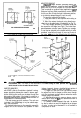
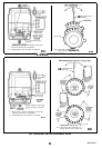
STROKE SEl-lING
On M94XXD,E,F motors, stroke is field adjustable and
can be set from 90” to 160”. Motors are shipped in 90”
position. In order to set stroke, both mechanical and elec-
trical adjustments are required. The mechanical adjust-
ments (cams) establish the full open (clockwise,
n
as
viewed from the power end) and full closed (counterclock-
wise
0
)
positions of the motor shaft. The electrical
adjustment (trim pot) provides sufficient total stroke angle
to ensure that cams will actuate both limit switches.
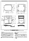
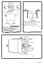
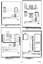
STROKE SETTING PROCEDURE
See Fig. 8.
Detach linkage from motor before adjusting stroke.
BEFORE SETTING STROKE:
1. Remove top cover from motor.
2. Disconnect controller from motor.
3. Connect
R,B,W
terminals on 135 ohm potentiome-
ter (Q209 or S963) to matching terminals on motor.
SETTING
160”
STROKE (Fig. 8):
1. Turn stroke pot fully clockwise
f7
.
2. Drive motor to mid-position using 135 ohm pot
(Q209 or
S963),
or by jumpering B-R-W.
3. Insert
l/8
in. screwdriver blade into slot on inner
yellow cam and MOVE TOP OF SCREWDRIVER as far as
possible counterclockwise
n
(viewed from power
end). Repeat in successive cam slots until inner cam is
against counterclockwise
0
stop.
8