


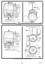

NON SPRING RETURN MOTORS
E373C
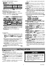
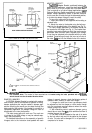
FIG. 2-LIMITS OF MOTOR ROTATION.
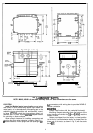
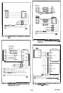
ADAPTER BRACKET
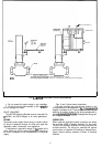
The220738A
Adaptor Bracket, positioned between the
motor and the equipment, raises the shaft height
ptthe-
M9484 motor by 0.75 inch to match that of the M941 motor.
This is required on all valve linkage applications,
Q607
External Auxiliary Switch applications, and on some
damper linkage applications (either to provide clearance
for the crank arm to rotate through the downward position,
or to allow the damper linkage to reach the shaft).
To mount the motor with the bracket:
1. Mount the bracket to the equipment with existing or
standard bolts.
2. Mount the motor to the bracket using the bolts pro-
vided into the threaded holes of the bracket (see Fig. 3).
For valve linkage applications, the bracket should first
be mounted to the linkage (see Fig. 4). The bracket then
provides a convenient base on which the motor can be
positioned. After the motor shaft is aligned to the linkage,
it can then be attached to the bracket with the 4 bolts
provided. These bolts go through the inner set of holes in
the motor
flanae
and into the threaded holes of the bracket.
n
1
#12 OR
l/4”
ZINC PLATED MACHINE SCREWS OR BOLTS
BOLTS
PROVIDED (4)
M
3076
FIG.
“MOUNTING
MOTOR WITH 220738A ADAPTER BRACKET. The
bracket is first mounted to the
equipmel
with standard bolts.
The motor is then mounted
to
the
bracket using the bolts provided with
the
bracKet,
which thread into the threaded bracket holes.
DAMPER LINKAGES
A 220738A Adapter Bracket is packed with replace-
ment motors. Use of this bracket is optional for many
damper applications but may be needed in damper appli-
cations requiring the crank arm to rotate through the
bottom plane of the actuator. If the bracket is not used in a
replacement application, the damper linkage will have to
be adjusted to the new shaft position.
The motor comes without a crank arm. The crank arm
is included in the Q605 linkage or may be ordered sepa-
rately (see Accessories).
For detailed instructions on the assembly of specific
linkages, refer to the instruction sheet packed with each
linkage. In general, however, check the following points of
operation when installing a motor and linkage.
1.
Linkages for valves and louver type dampers should
be adjusted so that the damper or valve moves through
only the maximum required distance when the motor
moves through its full stroke.
2. With modulating control, maximum damper
opening
should be no more than
60”.
Little additional airflow is
provided beyond this point.
3. The motor must be stopped at the end of its stroke
by the limit switch and must not be stalled by the damper
or valve. The motor will be damaged if it is not permitted to
complete its full stroke.
5
63-2195-l