


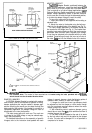
IMPORTANT
Set cams by moving top of screwdriver only. Press-
ing screwdriver against sides of cam slots could
cause damage to motor end switches.
4. Insert
l/8
in. screwdriver blade into slot on outer
yellow cam and MOVE TOP OF SCREWDRIVER as far as
possible clockwise
n
.
Repeat in successive cam slots
until outer cam is against clockwise
q
stop.
NOTE: Excessive force will damage cam stop on hub.
5. Check motor stroke before connecting linkage.
6. Disconnect 135 ohm pot, reconnect controller, re-
place top cover on motor.
7. Attach linkage to motor.
SETTING
90”
STROKE (Fig. 8):
1. Turn stroke pot fully counterclockwise
0
.
2. Drive motor to mid-position, using 135 ohm pot
(Q209 or
S963),
or by jumpering B-R-W.
3. Insert
l/8
in. screwdriver into slot on inner yellow
cam and MOVE TOP OF SCREWDRIVER as far as
possible clockwise
q
(viewed from power end). Re-
peat in successive cam slots until inner cam is against
clockwise stop.
NOTE: Excessive force will damage cam stop on hub.
4. Insert
l/8
in. screwdriver blade into slot on outer
yellow cam and MOVE TOP OF SCREWDRIVER
as
far as
possible counterclockwise
c
.
Repeat in successive
cam slots until outer cam is against counterclockwise stop.
NOTE: Excessive force will damage cam stop on hub.
5. Check motor stroke before connecting linkage.
6. Disconnect 135 ohm pot, reconnect controller, re-
place top cover on motor.
7. Attach linkage to motor.
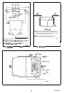
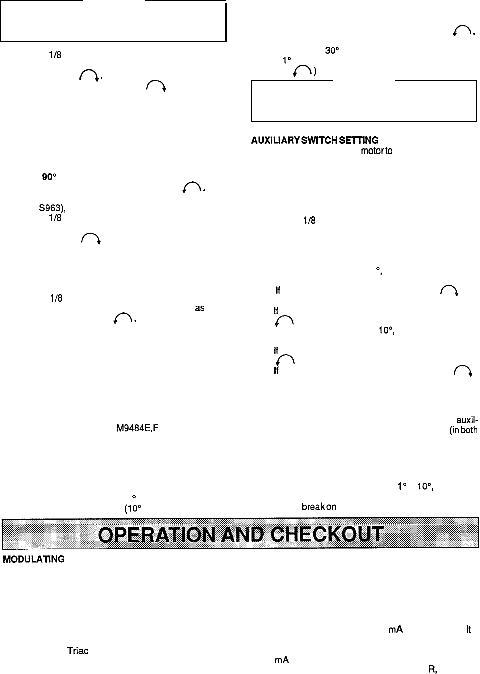
AUXILIARY SWITCHES
The auxiliary switches in
M9484E,F
motors are actu-
ated by adjustable cams. The cams are mounted on the
motor shaft at the power end of the motor. The settings of
the cams determine the point in motor shaft rotation at
which the auxiliary equipment will be switched on or off.
These cams can be set to actuate switches at any angle
within the stroke of the motor. Also each cam provides a
fast rise portion for switching (1
o
differential) and a slow
rise portion for slow switching (10’ differential).
Switching action and color coding are shown in Tables
1 and 2 on page 8.
Motors with factory added auxiliary switches are
shipped in the closed position (counterclockwise
fi
,
as viewed from power end) with auxiliary cams set to
actuate switches
30” from the closed position, and to
provide
1”
differential. Wiih motor in closed (full counter-
clockwise
r\
)
position, auxiliary switch breaks R-B.
IMPORTANT
Do not turn motor shaft by hand or with a wrench as
damage to the gear train and circuit board stroke
limit contacts will result.
AUXIUARY
SWlTCH
SElllNG
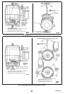
PROCEDURE (Fig. 9)
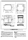
1. Removetopcoverfrom motorto gain access to motor
terminals and cam adjustments.
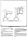
2. Disconnect controller from motor and connect 135
ohm manual potentiometer with R-W-B terminals on pot
connected to corresponding terminals on motor (Fig. 9).
3. Adjust 135 ohm pot so that motor shaft turns to
position where auxiliary equipment is to be switched.
4. Insert a
l/8
in., straight-blade screwdriver into slot on
cam associated with selected auxiliary switch. The inner
(blue) cam actuates the inner (right) switch, the outer (red)
cam actuates the outer (left) switch. MOVE TOP OF
SCREWDRIVER to set cams.
5. For switch differential of 1
O,
check continuity of aux-
iliary switch R-B contacts and rotate cam as follows:
a. lf
contacts are open, rotate cam clockwise
n
until
R-B contacts close.
b.
lf
contacts are closed, rotate cam counterclockwise
c
until R-B contacts open.
6. For switch differential of loo, check continuity of
auxiliary switch R-B contacts and rotate cam as follows:
a.
lf
contacts are open, rotate cam counterclockwise
0
until R-B contacts close.
b.
lf
contacts are closed, rotate cam clockwise
r\.
until R-B contacts open.
c. Final adjustment in the proper direction should be
made to obtain contact make or break at the desired
position.
7. Check for proper differential and switching of auxil-
iaryequipmentby runningmotorthroughfullstroke (inboth
directions), using 135 ohm pot. Repeat adjustment if
necessary.
8. Disconnect 135 ohm pot, reconnect controller, re-
place top cover on motor.
NOTE: If differential is changed from
1”
to
lo”,
the switch-
ing action is reversed, thus: switch contacts R-B make
and R-W
breakon
acounterclockwise (closed) rotation.
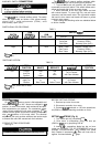
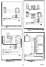
MODULATlNG
SERIES 90 CIRCUIT
CONNECTION DIAGRAMS (Figs. 10-13)
The potentiometers, one in the controller and one in the
These motors are designed for use in series 90 propor-
motor, along with resistor network, form a bridge circuit. As
tioning control circuits employing a 135 ohm series 90
long as the value of the controlled medium remains at the
controller. Series 90 high or low limit controls or manual
controller set point, the circuit is balanced, and the motor
minimum position potentiometers may also be used in the
does not run.
control circuit.
When the value of the controlled medium changes, the
potentiometer wiper in the controller is moved, which
unbalances the bridge circuit. This unbalance is amplified,
and energizes
Triac switching to run the motor in the
direction necessary to correct the change in temperature
or pressure. The motor turns the feedback potentiometer
to rebalance the circuit and stop the motor.
The M9484 can also be used with some electronic
controllers which provide a 4-20
mA
control output.
lt
is
necessary to use a resistor kii (4074EED for controlling up
to 6 motors) or Q7230 Interface Module to interface to the
4-20
mA
source.
The standard series 90 controller has
R,
W, and B
terminals. As the controller reduces Rto W resistance, the
motor will drive closed (CCW as viewed from the power
end).
10