


Y
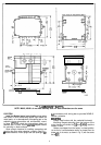
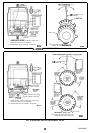
BOLTS PROVIDED (4)
WIRING BOX
MOTOR
MACHINE SCREWS OR BOLTS.
LTS SECURING BRACKET TO LINKAGE.
M
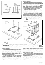
31% TIGHTEN AFTER SECURING MOTOR TO THE BRACKET USING FOUR BOLTS PROVIDED.
FIG. 4-MOTOR
MOUNTING
ONVALVE LINKAGE,.
4.
Do not exceed the motor ratings in any installation.
5.
Do not turn motor shaft manually or with a
wrench-
this will damage the motor.
VALVE LINKAGES
The 220738A Mounting Bracket must be used with the
Ql
00,
Q601 and Q618 linkages in all valve applications.
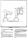
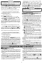
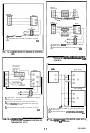
Figs. 5 and 6 show internal schematics.
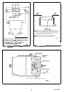
The motor terminals are quick-connects located on top
of theprintedcircuit boardshown in
Fig.7.Ascrewterminal
adapter is standard on all Trade models and also may be
added to all models. Access to the wiring compartment is
gained
byremovingthe4screws
inthetoppf the wiring box
and lifting off the cover.
WIRING
Disconnect power supply before wiring to prevent electri-
cal shock or equipment damage. All wiring must agree with
applicable codes, ordinances, and regulations.
A transformer is required to supply 24
Vat power to the
motor. Make sure that the power requirements stamped on
the motor correspond to the characteristics of the power
supply.
WIRING BOX
When used with liquid-tight conduit connectors, the wiring
box provides NEMA 3 weather protection for the motor.
The box also provides knockouts for wiring conduits and
encloses terminals. The wiring box, standard with replace-
ment motors, is required for housing an internal trans-
former, internal auxiliary switches or Series 70 Interface
Modules.
6