


AUXILIARY SWITCH RATINGS (amperes):
M94XXE
has 1 spdt switch.
M94XXF
has 2 spdt switches.
ONE CONTACT
a
120v 240v
Full Load 7.2 3.6
Locked Rotor 43.2 21.6
a4O
VA pilot duty, 1201240
Vat
on opposite contact.
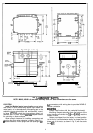
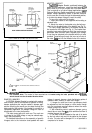
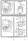
DIMENSIONS: See Fig. 1.
UNDERWRITERS LABORATORIES INC. LISTED
File No. E4436; Guide No. XAPX.
CANADIAN STANDARDS ASSOCIATION CERTIFIED:
General Listing File No.
LR1620,400-E-)
‘U
STROKE STROKE RUNNING
BREAKAWtY
15
set
30
set
75
18.51
150
[17.0]
30
set
1 min 150
[17.0]
300
[34.0]
1.2 min
1
2,4
minD
1
300 134.01
1
600 168.01
aBreakaway
torque is the maximum torque available to
overcome occasional large loads such as a seized
damper or valve. MOTOR MUST NOT BE USED
CONTINUOUSLY AT THIS RATING.
bStalling
of
2,4
min motor will damage motor.
ACCESSORIES:
ES6501 17 Explosion-proof Housing-Encloses motor
for use in explosive atmospheres. Not for use with
Q601,
Q618, and
Q455
Linkages. Order from Nel-
son Electric Co. Requires Honeywell
7617DM
Cou-
pling.
Q607 External Auxiliary Switch-Controls auxiliary
equipment as a function of motor position.
Q605 Damper Linkage-Connects motor to damper.
INCLUDES MOTOR CRANK ARM.
0618 Linkage-Connects Modutrol motor to water or
steam valve.
Q601 Bracket and Linkage Assembly-Connects
Modutrol motor to water or steam valve.
Ql
OOA,B
Linkage-Connects Modutrol motor to
but-
terfly valve. Requires adapter bracket packed with
motor.
Q209E,F
Potentiometer-Limits minimum position of
motor.
Q68 Dual Control Potentiometer-Controls 1 through 9
additional motors.
Q181 Auxiliary Potentiometer-Controls 1 or 2 addi-
tional motors.
221455A
Motor Crank Arm-Infinitely adjustable crank
arm. Approximately 0.75 inches shorter than the
4074ELY crank arm, can rotate through downward
position and clear base of motor without requiring
use of adapter bracket.
220741A Screw Terminal Adapter-converts the stan-
dard quick-connect terminals to screws terminals.
Transformers-mounted internally, provide 24 Vat
power to motor
198162JA-24 Vat;
50/60
Hz (for electrical iso-
lation).
198162EA-120
Vat;
50160
Hz.
198162GA-220 Vat;
50160
Hz.
198162Al-120/208/240 Vat;
50160
Hz.
Q7130A-Interface Module with selectable voltage
ranges (4-7 Vdc, 6-9 Vdc, and 10.5-13.5 Vdc).
Adapts motor to M71 XX function.
Q7230A-Interface Module, selectable voltage or cur-
rent control, with adjustable null and span. Adapts
motor to
M72XX
function; 4 to 20
mA
or 2 to 10 Vdc.
Q7330A-Interface Module, for W936 economizer ap-
plications. Adapts motor to
M73XX
function.
Q7630A-Interface
Module, 3-wire 14-17 Vdc control
with minimum position capability. Adapts motor to
M76XX
function.
4074BYK-Control up to 6 M9lXX motors in unison
from one Series 90 controller.
4074EAU-Drive 2 or 3
M91
XX motors from a W973
Single-zone Logic Panel or
W7100
Discharge Air
Controller.
4074EDC-Drive one
M91XX
motor from a 4-20
mA
Controller.
4074EED-Drive up to 4
M91
XX motors from a 4-20
mA
Controller.
221508A
Resistor Board-Plugs onto quick-connects
in wiring box of M9lXX motor. Can be used in place
of
4074BYK,
EAU, EDC, or EED resistor kits (func-
tions described above).
7616ADW Motor Crank Arm-Approximately 0.75
inches shorter than the 7616BR crank arm, can
rotate through the downward position and clear
base of motor without requiring use of adapter
bracket.
them could damage the product or cause a hazardous
condition.
2. Checkthe
ratings given in the instructions
andon
the
product to make sure the product is suitable for your
application.
3. Installer must be a trained, experienced service
technician.
4. After installation is complete, check out product
WHEN INSTALLING
THIS PRODUCT...
1. Read these instructions carefully. Failure to follow
1.
2.
3.
operation as provided in these instructions.
1
Disconnect power supply before beginning
in-
stallation to prevent
eiectrical
shock and equip-
ment damage.
Never turn the motor shaft by hand or with a
wrench-this will damage the motor.
Always conduct a thorough checkout when in-
stallation is complete.
3
63-2195-l