


C7027A, C7035, C7044A, C7927A MINIPEEPER® ULTRAVIOLET FLAME DETECTORS
9 60-2026—11
g. The scanner wires should remain separated a
minimum of two in. (51 mm) from other line voltage
wires in the main control panel to the flame
safeguard device.
3. Avoid installation considerations that can influence
detector operation and maximum leadwire length, such
as:
a. Moisture.
b. Ignition interference.
c. High resistance connections—poor grounds.
d. Leadwire capacitance.
e. Voltage fluctuations.
f. Induced line transients.
g. Floating grounds—ground at some voltage above
earth ground.
h. No G wire—burner used as ground.
i. Detector output less than maximum attainable for
the installation (inadequate sighting.
IMPORTANT:
Do not run the flame detector wiring in the same
conduit with high voltage ignition transformer wires.
Connecting Detectors In Parallel
For a flame that is difficult to sight, using two flame detectors
connected in parallel will reduce the occurrence of nuisance
shutdowns. If only one of the parallel detectors loses the flame
signal, the other will continue to indicate the presence
of the flame and keep the burner in operation.
When the flame detectors are connected in parallel, the low
level background signals are additive. Therefore, no more
than two C7027A, C7035A, or C7044A Flame Detectors
should be paralleled. Furthermore, the background signal
increases as temperature decreases. Because of this, the
minimum ambient operating temperature must be increased
when the C7027A, C7035A or C7044A Flame Detectors are
paralleled.
When using detectors rated for a minimum of 0°F (-18°C),
limit the minimum ambient temperature at the detectors to
32°F (0°C). When using detectors rated for a minimum of
-40°F (-40°C), limit the minimum ambient temperature at the
detectors to -10°F (-23°C).
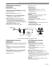
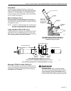
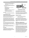
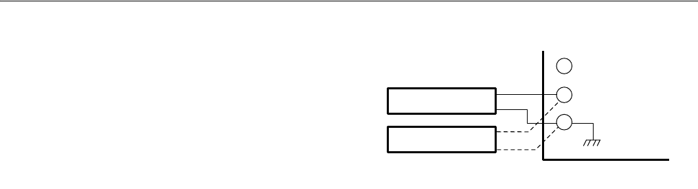
Connect the blue leadwires of both detectors to the F terminal
of the wiring subbase or terminal strip, and the white
leadwires of both detectors to the G terminal, as shown in
Fig. 10.
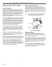
Earth Ground
The detector and the flame safeguard control must be
connected to earth ground. A convenient method of
accomplishing this is to connect the detector to the flame
safeguard control with a flexible conduit, or ensure a good
ground connection at the mounting bracket.
Fig. 9. Wiring C7027A, C7035A, and
C7044A flame detectors in parallel.
ADJUSTMENTS AND CHECKOUT
Before welding the C7027A, C7927A or C7035A sight pipe
in its final location, or before tightening the C7044A clamp
screw, complete both the adjustments and checkout tests that
follow and any required by the burner manufacturer.
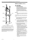
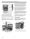
Uv Sensor Tube Test
NOTE: For initial burner lightoff, consult the burner
manufacturer instructions or the instructions
for the flame safeguard control.
During the initial burner lightoff, make sure the flame
safeguard control starts (i.e., the load relay, usually 1K,
pulls in). If it does not start, visually check the sensing tube in
the C7027A, C7035A, or C7044A flame detector. If the tube
continues to glow when no flame is present, replace the
sensing tube (C7035A), or replace the detector (C7027A or
C7044A).
Adjust Detector Sighting Position
With the flame detector installed and burners running, adjust
the position of the flame detector for optimum flame signal.
The flame signal will be read in microamps or voltage (Vdc)
depending on the Honeywell flame safeguard combustion
control used.
Most existing Honeywell flame safeguard controls incorporate
a flame current jack on the flame amplifier or on the control
itself. The flame signal can be measured with a volt-ohmmeter
such as the Honeywell W136A. To measure the flame current
(signal), use a cable connector (part number 196146, included
with the W136A) in conjunction with the meter. With the
W136A (or equivalent) positioned at the zero to 25
microampere scale, make connections from the meter probes
to the two ends of the cable connector plug (red to red, black
to black). Make these connections before inserting the plug
end of the connector plug into the flame jack of the control
or control amplifier (see Fig. 11). Read the flame signal in
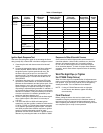
microamperes directly from the W136A meter. Refer to
Table 1 for the minimum acceptable flame currents.
M3018
F
WIRING SUBBASE
OR
TERMINAL STRIP
OPTIONAL
SECOND
DETECTOR
UV DETECTOR
UV DETECTOR
BLUE
BLUE
WHITE
WHITE
G