


C7027A, C7035, C7044A, C7927A MINIPEEPER® ULTRAVIOLET FLAME DETECTORS
60-2026—11 8
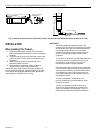
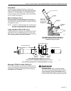
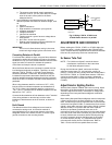
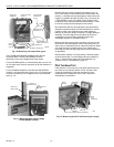
Fig. 8. Mounting C7044A Detector on blast tube.
The C7044 is mounted in a 29/32 in. (23.0 mm) hole in the
blast tube. The mounting bracket is fastened to the blast tube
with 2 screws on 1-27/64 in. (36.1 mm) centers.
The mounting bracket is designed so that the detector can be
removed from the blast tube for cleaning and then replaced
without disturbing the sighting angle. Loosen the 2 screws
holding the bracket to the blast tube, but do not loosen the
clamp screw on the bracket. Twist both the bracket and
detector to remove them.
WIRING (ALL MODELS—FIG. 10)
CAUTION
Equipment Damage Hazard.
Can cause improper operation.
The blue (tan with blue tracer with C7035A1080)
leadwire must be connected to the F terminal of the
flame safeguard control subbase or terminal strip
and the white (tan leadwire without blue tracer with
C7035A1080) to the G terminal (see Fig. 10).
Failure to observe the circuit polarity by reversing
the leadwires (even momentarily) may cause the
flame detector to improperly supervise the combustion
flame.
IMPORTANT
All wiring must comply with applicable local electrical
codes, ordinances and regulations. Use NEC Class
1 wiring.
The detector has color-coded and labeled, plastic-insulated,
no. 18 AWG leadwires, eight ft. (2.44 m) long, rated for 221°F
(105°C).
1. Keep the flame signal leadwires as short as possible
from the flame detector to the terminal strip or wiring
subbase. Capacitance increases with wire length,
reducing the signal strength.
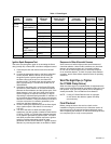
NOTE: The maximum permissible leadwire length depends
on the type of leadwire and the conduit type and
diameter. The ultimate limiting factor in flame signal
leadwire length is the signal current or voltage at the
flame safeguard device. See Table 1.
2. If needed, splice detector leadwires for longer leadwire
runs, observing the following considerations:
a. Make required splices in a junction box.
b. Use moisture-resistant no. 14 wire suitable for at
least 167°F (75°C).
c. For high temperature installations, use Honeywell
Specification no. 32004766-003 or equivalent for
the F leadwire. This wire is rated up to 400°F
(250°C) for continuous duty. It is tested for operation
up to 20 Kv and for breakdown up to 35 Kv. For the
other leadwires, use moisture-resistant no. 14 wire
selected for a temperature rating above the
maximum operating temperature.
d. F and G wires must be run in their own conduit
independent of other power carrying leadwires.
More than one scanner F and G wire can be run in
the same conduit.
e. A shielded twisted pair wire may be substituted for
using conduit for routing the F leadwire. Be advised
of the capacitance per foot of shielded wire
effectively reduces the flame signal at the flame
safeguard device. Be sure to ground the shield to
the G terminal at the flame safeguard wiring
subbase.
f. The detector wires need to be run in their own
conduit as well, avoiding other electrical noise
carrying wiring.
1-27/64 IN.
(36.1 mm)
8
-32 RHIS
(
EUROPEAN M-4)
S
CREW (2)
29/32 IN. (23.0 mm)
MOUNTING HOLE
IN BLAST TUBE
MOUNTING
BRACKET
C7044A
DETECTOR
CLAM
P
SCRE
W
M3020