


C7027A, C7035, C7044A, C7927A MINIPEEPER® ULTRAVIOLET FLAME DETECTORS
60-2026—11 10
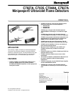
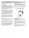
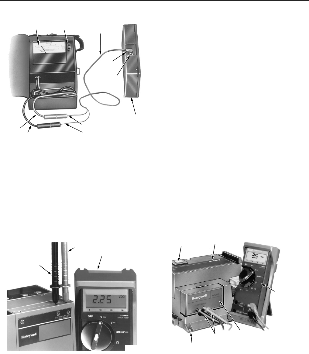
Fig. 10. Measuring microamp flame signal.
The R7749B and R7849A,B Amplifiers used with the
Honeywell BCS 7700 and 7800 SERIES controls,
respectively, have a dc voltage flame signal output.
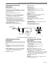
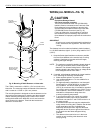
For the R7749B Amplifier, a volt-ohmmeter with a zero to 5 or
10 Vdc scale and a minimum sensitivity of 20,000 volts/ohm is
suggested.
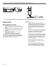
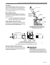
For the R7849A,B Amplifiers used with the 7800 SERIES
controls, a volt-ohmmeter with a zero to 5 or 10 Vdc scale and
a minimum sensitivity of one megohm/volt is recommended,
(see Fig. 12).
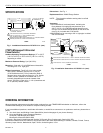
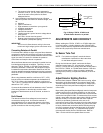
Fig. 11. Measuring flame signal voltage
of 7800 SERIES controls.
Measure the flame signal voltage as illustrated in Figs. 12
and 13. Be careful to connect the positive meter lead to the
positive (+) amplifier jack and the negative meter lead to the
negative (-) amplifier jack (BCS 7700) or the (-Com) jack for
a 7800 SERIES control. If the BCS 7700 and Series 7800
controls have the optional Keyboard Display Module, a zero
to five Vdc reading will be displayed on the module.
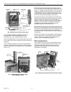
Move the flame detector and sight pipe (if not permanently
attached to the burner/boiler) to view the flame from various
positions. Allow a few seconds for the meter reading to
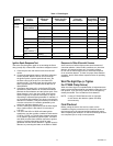
stabilize. A maximum steady microamp or voltage reading is
desirable. The flame signal must be above the minimum
acceptable level for the flame safeguard control and
associated amplifier as indicated in Table 1.
Measure the flame signal for the pilot alone, the main burner
flame alone, and both together (unless monitoring pilot only
when using an intermittent pilot or supervising the main flame
only when using direct spark ignition). Also, measure the
flame signal at low and high firing rates and while modulating
(if applicable).
With the flame detector in its final position, all flame signals
must be steady with a current/voltage value as indicated in
Table 1. If the minimum signal cannot be obtained or is
unstable, refer to Troubleshooting, page 10.
Pilot Turndown Test
If the detector is used to prove a pilot flame before the main
fuel valve can be opened, perform a Pilot Turndown Test.
Follow the procedures in both the Instructions for the
appropriate flame safeguard control, and in the burner
manufacturer's instructions.
Fig. 12. Measuring the BCS 7700 flame signal voltage.
W136A VOLT-
OHMMETER
W136A SELECTOR
SWITCH
196146 METER
CONNECTOR
PLUG
PLUG
PLUG-IN FLAME
SIGNAL AMPLIFIER
FLAME SIGNAL
METER JACK
RED CONNECTOR
BLACK CONNECTORBLACK (–) METER LEAD
RED (+)
METER
LEAD
M6532A
NEGATIVE (-)
METER LEAD
POSITIVE (+)
METER LEAD
ONE
MEGOHM/VOLT
METER
M7382
RESET
BUTTON
PROGRAM
MODULE
20,000
VOLT-
OHMMETE
R
BCS 7700 CHASSIS MODULE FOOTMOUNT
METER
PROBES
FLAME
AMPLIFER
M7860